Features of the Cobra collimator sight
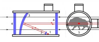
All Cobra collimator sights have a fundamentally repeating optical design, the differences in which can only lie in the method of attachment to the weapon. The design of the sights is open, and the formation of the aiming mark is carried out by a laser.
A detailed overview of the collimator, with an emphasis on its strengths and weaknesses, is shown in the video:
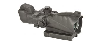
The body of the device is made of aluminum alloy, which allows you to slightly reduce the weight of the rather bulky design. The tightness of the sight is ensured by a tight fit of parts and the use of polymer seals, allowing operation in any weather.
The only drawback when used in the rain is the blurring of the aiming mark due to water falling on the lens and filling the laser beam channel with it. Excess moisture is removed by wiping with a dry cloth, after which the sight is ready for use again.
The warranty operating time when installed on a military (hunting) weapon is 1200 shots. If a collimator sight is used on pneumatics (including airsoft), then the number of shots fired does not affect the degree of wear.
When purchasing a sight with batteries rather than a built-in battery, do not forget to replace them regularly (without waiting until they are completely discharged).
If the collimator is mounted on a firearm, the strong recoil will distort the batteries and they may leak inside the device.
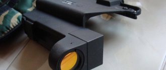
A visual feature of the sight is the partial overlap of the aiming field with the vertical adjustment screw. This does not interfere with the effective use of the collimator, but it does take time for the shooter to get used to this design.
Cobra collimator sight. Manual.
6. General instructions 6.1 Before using the sight, you must use a rag to remove the grease from the weapon attachment device, the heads of all screws (Appendices A...D) and the screwdriver key. Wipe the lenses in a circular motion from the center to the edge with the clean cloth included with the scope. 6.2 Check: - turning the power on and off; — rotating the horizontal correction knob left and right all the way and the range input knob all the way to the right from the original position; — switching the types of aiming marks and the brightness of their glow. 6.3 The sight is hermetically protected from the penetration of dust and moisture into the body. In addition, all threaded connections are secured against self-unscrewing. To avoid depressurization and damage to the locking system, it is prohibited to disassemble the sight, therefore all repair work associated with disassembling the sight must be carried out by trained specialists in a workshop. Unauthorized disassembly will void the warranty on the scope.
7. Preparing the sight for operation 7.1 Installing the battery. To install (replace) the battery, use a screwdriver to unscrew the power compartment cover 3 (Figure 1) in the “O” direction (open) and remove it from the socket. Then remove the used one and install a new battery, strictly observing the polarity indicated on the central contact of the battery. After this, install cover 3 into the slot and screw it until it stops in the “Z” direction (closed). The power is turned on and off using knob 4 (Figure 1), by setting it to position “B” (on) or to position “O” (off). If, after turning on the power, the image of the aiming mark is not observed, then you should press key 6 several times in the direction of the “+” sign or check that the batteries are installed correctly. The type of mark is selected by successively pressing button 5. The optimal brightness of the aiming mark is set by pressing key 6 (Figure 1). A single press on one of its arms in the direction of the “+” or “-” signs results in an increase or decrease in brightness, respectively, by approximately half the previous value.
8. Alignment procedure and operation with the sight 8.1 After becoming familiar with the device and operating principle, the sight must be adjusted to the weapon with which it will be used. 8.2 Zeroing is carried out at a distance of 100 m at a shooting range or shooting range. Shooting is carried out from a weapon fixed in the machine, or from a prone position from a rest at a sighting target mounted on a white shield measuring 1.0 x 1.0 m, cut out of paper or cardboard with a black circle with a diameter of 25 cm and a marked center. ATTENTION! The aiming point is the center of the circle. The aiming process involves aligning the “Dot” type reticle with the center of the target. 8.3 To zero the sight on the weapon, several series of 4 single shots are fired. If, based on the results of a series of shots, the average point of impact (MIP) is located above (lower), left (right) of the center of the target, then it is necessary, using vertical and horizontal alignment devices (see Figure 2), to shift the MIP lower (above), to the right (left) on the measured deviation of the STP from the aiming point, it should be borne in mind that the cost of one division of the sighting scales when zeroing at a distance of 100 m is equal to 3 cm. The STP is determined as follows: for every 4 shots from a weapon aiming at the center of the target circle of the point hits are connected in pairs by two non-intersecting straight line segments. The midpoints of the resulting segments are connected to each other by a straight line segment. The midpoint of this segment is the STP. The sight is considered zeroed if the average point of impact (MPO) is located in the area of a circle with a diameter of 10 cm with the center at the aiming point with normal combat accuracy. Accuracy is considered normal, in which all 4 holes, in extreme cases - 3, with one torn off, fit into a circle with a diameter of 15 cm. After zeroing in on the weapon, the sight is ready for use. When aligning the sight, you should be guided by clauses 8.4...8.7. 8.4 To perform vertical alignment when zeroing, you should (see Figure 2): a) holding handle 3 with one hand, use a screwdriver to unscrew lock nut 1 approximately 1 ... 2 turns; b) lift the handle 3 up, prying it by the edge with a screwdriver, to disconnect it from contact with the conical surface of the lead screw 2; c) holding handle 3, turn the lead screw 2 with a screwdriver key in the direction of the displacement of the STP along the arrow indicated on the outer end of the handle 3, by the number of scale divisions corresponding to the vertical displacement of the STP, orienting the slot of the screw 2 along the marks of the divisions on the handle 3. 8.5 By At the end of the vertical alignment, you should (see Figure 2): a) align the number “0” of handle 3 with the fixed mark on the sight body; b) tighten lock nut 1, pressing handle 3 down and making sure that screw 2 does not turn. 8.6 To perform horizontal alignment when zeroing, you should (see Figure 2): a) holding handle 5 with one hand, use a screwdriver to unscrew lock nut 6 approximately 1 ... 2 turns; b) lift the handle 5 up, prying it by the edge with a screwdriver to disconnect it from the conical surface of the lead screw 7; c) holding handle 5, turn the lead screw 7 with a screwdriver key in the direction of the displacement of the STP along the arrow indicated on the outer end of the handle 5, by the number of scale divisions corresponding to the horizontal displacement of the STP, orienting the slot of the screw 7 along the marks of the marks on the handle 5. 8.7 By At the end of the horizontal alignment, you should (see Figure 2): a) align the number “O” of handle 5 with the fixed mark on the sight body; b) tighten lock nut 6, pressing handle 5 to the left and making sure that screw 7 does not turn. 8.8 If during operation there is a need to change the firing range, then the firing range can be changed by turning knob 3 (Figure 2). The number of divisions by which knob 3 must be turned is determined by the ballistic characteristics (or experimentally) of a particular weapon. ATTENTION! Rotation of the handles 3.5 can be made from one fixed position to another to the right or left until it stops. 8.9 It is not recommended to remove handles 3 and 5 during operation, as this may lead to loss of the latch parts - the ball and spring. Upon completion of work with the sight, switch switch 4 (Figure 1) to the “O” position. It is recommended to use the T-shaped reticle as a rangefinder, given that the vertical dimension of the T-shaped reticle corresponds to approximately 140 cm at a distance of 100 m.
9. Checking the technical condition 9.1 Checking the technical condition must be carried out periodically, depending on the degree and nature of its operation, guided by section 6 of this document.
10. Typical malfunctions and methods for their elimination
table 2
| Type of malfunction | Possible reason | Elimination method |
| When the sight is turned on, the mark does not light up | The battery life is exhausted or the polarity of the element installation is incorrect | Replace the battery, observing the correct polarity |
| The stamp glows, but the brightness is insufficient | Supply voltage reduced | Replace battery |
11. Maintenance of the sight 11.1 When removing the sight from the weapon, before putting it in the case, you must inspect and wipe the sight with a clean rag, while the lenses should be wiped in a circular motion, from the center to the edge, only with the napkin included in the scope delivery package. After water gets on the scope, it must be wiped dry with a rag and dried. Simultaneously with cleaning and lubricating the weapon or before placing the sight in the case, lubricate the mounting device to the weapon, the heads of all screws (Appendices A...D) and the screwdriver key with plastic grease GOI-54P GOST 2376-89.
12. Storage rules 12.1 In order to ensure the functionality and required characteristics of the sight, you should: - protect it from falls, sharp blows, shocks; — store in dry and heated rooms at temperatures from +8°C to +35°C, relative humidity no more than 85%.
13. Manufacturer's guarantees 13.1 The manufacturer guarantees that the quality of the sight meets the technical requirements provided that the consumer complies with the operating and storage conditions specified in the operating manual.
13.2 Warranty shelf life is 7 years from the date of release of the sight. The warranty period is 2 years from the date of sale through a retail chain if there is a stamp of the trading organization and the date of sale in the passport; if they are absent, from the date of release of the sight. The guaranteed time between failures is 1200 shots within the warranty period. If the sight fails during operation during the warranty period, the manufacturer will repair or replace the sight and its components free of charge. Batteries are not subject to warranty. Appendix A (mandatory) Device for attaching a sight to a weapon with an eccentric body 1, stop 2, adjusting screw 3, locking screw 4, movable block 5, lever with an eccentric 6 Figure A.1 - Device for attaching a sight to a weapon with an eccentric
- Installing a sight on a weapon:
- set the eccentric lever 5 in the direction of the butt of the weapon;
- unscrew locking screw 4 by 2-3 turns;
- unscrew adjusting screw 3 by 2-3 turns;
- place the sight, combining the dovetail of the body 1 and the movable block 5 with the dovetail of the weapon seat, move the sight along the bar until its position is fixed with stop 2;
- secure the sight to the weapon by turning the eccentric lever 5 in the direction of the weapon barrel.
Optimal fastening of the sight is ensured by adjusting screw 3. After securing the sight, screw locking screw 4 until it stops. In the EKP-8-15 sight, instead of stop 2, there is a limiter, which must fit into the groove of the mounting bar on the weapon.
Appendix B (mandatory) Device for attaching the sight to the weapon: side housing 1, adjusting screw 2, movable block 3, lever with eccentric 4, stop 5 Figure B.1 - Device for attaching the sight to the weapon
- Installing a sight on a weapon:
- before installation on the weapon, the stop 5 of the sight mounting device must be in a retracted position towards the butt and pressed against the body 1;
- push the sight from the butt side all the way onto the side bar located on the left side of the weapon;
- turn the stop 5 180 degrees towards the barrel, while pressing down on the stop 5, place the protrusion of the stop 5 behind the body 1.
In this case, the sight must be tightly secured to the weapon strap. If necessary, adjust how tightly the sight is secured to the side rail of the weapon. The need for adjustment arises in the following cases: — the protrusion of the stop 5 does not move behind the body 1 even with a significant force on the stop 5; — the protrusion of the stop 5 is inserted behind the body 1, but the sight is not tightly secured to the side rail of the weapon. If the protrusion of the stop 5 does not engage the housing 1:
- turn the stop 5 at an angle of approximately 90 degrees towards the butt. Rotate the movable block 3 relative to the stop 5 by approximately 90 degrees, move it towards the hole and remove the block 3;
- Without removing the sight from the weapon, remove the stop 5 from the slots of the adjusting screw 2, install the stop 5, moving it several teeth towards the barrel (to reduce the force on the stop 5) together with the lever 4;
- install the cracker 3 in its original place with the fixing protrusion downwards, inserting it into the hole on the stop 5. Place the stop 5 with the protrusion behind the body 1, pressing down on the stop 5.
- If the sight is not tightly secured to the side rail:
- shift the stop 5 by several teeth towards the butt together with the lever 4;
- install the cracker 3 in its original place with the fixing protrusion downwards, inserting it into the hole on the stop 5. Place the stop 5 with the protrusion behind the body 1, pressing down on the stop 5.
Appendix B (mandatory) Screw mounting device for the sight to the weapon with a nut
Figure B.1 — Device for attaching the sight to the weapon
- Installing a sight on a weapon:
- unscrew the nuts 2 until they stop against the screws 3;
- position the sight, aligning the “dovetail” of the rack 1 with the “dovetail” of the weapon seat, making sure that the protrusions of the mount coincide with the semicircular depressions of the racks 1;
- tighten nuts 2 tightly, while the dovetail of teeth 4 and crackers 5 should coincide with the dovetail of the weapon seat.
Appendix D (mandatory) Screw mounting device for the sight to the weapon
bracket 1, strap 2, screw 3 Figure D.1 — Device for attaching the sight to the weapon
Fastening
Cobra collimator sights are modern sighting devices that use the entire range of domestic and foreign-made mounts. On air guns, the most commonly used are the Picatinny (Weaver) rail and the dovetail located on top of the receiver (with a width of 11 or 12.5 mm). Installation on the seat does not require lengthy manipulations and consists of turning the locking levers or tightening the fastening nuts.
In addition to standard fastenings, there is a fixation on the side dovetail (on the left side) and a similar horizontal fastening in the upper part, 7 mm wide. If the weapon does not fit into the transport case with the scope attached, then the latter can be removed without the need for re-zeroing.
Using digital control in the Cobra sight
The digital control circuit allows you to implement a flexible system of settings in the operation of the sight. In total, the collimator provides 4 types of aiming marks, the intensity of which can be varied in sixteen brightness levels.
After turning off the sight, the preset setting is not lost. Changing the type of reticle does not change the location of the central target designator, keeping the average point of impact unchanged.
In analog circuits, it is difficult to achieve constant settings without using an even more massive design. The implemented digital system is compact and resistant to various types of shock loads.
These are open sights that are extremely convenient to use. We're talking about holographic sights here. Let's look at the design and operating principle of holographic sights and make a brief overview of some models. In this review you can watch a video about the Matador air rifle, as well as study the characteristics and application features.
Model overview
EKP-8-02
Collimator sight Cobra EKP-8-02
The sight has a side mounting system (similar to the previous model), suitable for numerous types of weapons. As with other models of collimators, unmasking of the shooter from the target side due to the working laser is completely excluded. The location of the switching elements in hard-to-reach places protects against accidental pressing, slightly worsening the ergonomics when changing settings frequently.
EKP 8 -18
Collimator sight Cobra EKP 8 -18
The differences between this model are the mounting method. The sight system allows it to be fixed on weapons equipped with a Picatinny (Weaver) rail. This allows the device to be used in conjunction with most foreign air rifles, as well as airsoft weapons that imitate the weapons of NATO countries. Has good reviews.
If appropriate fastening is not available, special adapter strips can be used. Considering the initially small dimensions of the sight, their use will not significantly increase the dimensions of the weapon or raise the line of sight.
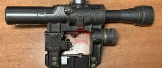
EKP-1S-03
Collimator sight Cobra EKP-1S-03
This collimator model is equipped with a side sighting bar and is intended for installation on a hunting firearm or airsoft weapon (SVD, SVD-U, AK with a side rail). The sight is equipped with a convenient lever locking system, which reduces the time it takes to bring the rifle or drive into the firing position.
You can evaluate the ergonomics of the sight and its appearance parameters in the video:
"Cobra" on a raid hunt
Photo by Alexander Gorbachev
Afterwards, analyzing the mistakes I had made, I realized that when shooting a bullet from a smoothbore gun, it can be difficult to take aim at a moving target. Either the eyes are no longer the same due to old age and working on a computer; or something else...
Unexpectedly, one friend gave me a “Cobra” EKP-1S-03 collimator sight, unprepossessing in appearance, it’s clear that it was invented for a serious weapon. After turning it this way and that, I went online and began to figure out how to adapt it to the TOZ-120 with a vertical barrel arrangement and a ventilated sighting rib.
It turned out that to install the Cobra on a gun you need a Weaver rail, which can also be purchased via the Internet. Critical in this case is the width of the sighting bar, on which the Weaver rail is attached with two pairs of slotted bolts. The sight has variable brightness of several types of reticle: there is a dot, a cross, and a triangle with a dot - to choose from. It seemed to me more convenient to have a point that, in bright light, is displayed at high brightness and at the same time does not overlap the target - the figure of an animal at a distance of 40-50 meters.
Then the main question arose: how to zero the scope without wasting a lot of ammunition? To save ammunition, there is “cold” zeroing using “laser” cartridges. However, having inserted such a cartridge into the barrel, I was surprised to find that it not only dangled in the chamber, but also did not allow the gun to be closed.
Fortunately, it turned out that the front sight and rib were visible through the gap between the Weaver rib and the rib. Gently holding the gun in a clamp by the block, we combine the aiming bar and the front sight with the selected target. After that, we look through the scope, finding the aiming mark. It's good if it coincides with the chosen goal. If not, we begin to turn the dials according to the instructions: up and down and left and right.
At first it seems extremely inconvenient to invest in, after all, this sight was invented for other types of weapons, but you can get used to it. Special convenient collimator sights from serious companies are much more expensive, and cheap Chinese ones can fail at any time.
Here it is worth mentioning the principle of operation of a collimator sight: a laser source of coherent radiation forms an aiming mark at infinity, which coincides with the aiming line and is aimed at the target.
Aiming can be done with your eyes open; the displacement of the eye relative to the sight does not affect the result of the shot, since you only have to combine the aiming mark and the target area. For long-range shots, 100 meters or more, there are two dials that set vertical and horizontal corrections. However, this is not necessary for a smooth-bore gun, but for a rifled gun it is better to install an optical sight for such shots.
So, what do we have in the bottom line? We have reliability, convenience of “cold” sighting, operation from a power source for up to 70 hours. The downside is that it looks unsightly.
Last year I had the opportunity to test the Cobra on a driven elk hunt. The fourth, apparently the last, corral is underway. The day is already ending, everyone is tired. In the previous three drives, the elk moved either through the beaters or to the side of the shooting line. About twenty minutes had already passed, and something cracked in front of me. The sight is constantly on, the safety is on.
Suddenly, from the left, about forty meters away, an elk lunges onto the road and pauses, trying to determine the impending danger. The gun rests on the shoulder as usual, the aiming mark finds the target. I can clearly see the animal with both eyes and a point on the elk’s shoulder.
The shot, I feel it hit the spot, and I shoot again without changing the position of the gun. The animal slowly moves across the road and, having stumbled, falls into the snow. The bullets landed at a distance of 10–15 centimeters from each other, one shattered the shoulder joint, and the other broke the heart.
This is how “import substitution” turned out!
Nikolay Sorokin February 1, 2016 at 10:55
Model characteristics
| Characteristics | Model | ||
| EKP-1S-03 | EKP-8-02 | EKP 8 -18 | |
| Magnification, times | 1 | ||
| Angle of field of view when aiming with one eye, degrees. | 6 | ||
| Field of view when aiming with two eyes | Not limited | ||
| Dimensions (length × width × height), mm | 144 × 66 × 144 | 154 × 46 × 151 | 154 × 46 × 85 |
| Weight, kg | no more than 0.410 | ||
| Continuous operation time of the illuminator, hour | 70 | ||
| Aiming range | Fundamentally unlimited | ||
| Supply voltage, V | 3 (2 x 1.5 V batteries) | 3 (1 battery) | |
| Operating temperature range, ° C | -40…+50 | ||
| Angular size of the dot-type aiming marker, ang. minutes | 1.8 (about 5 cm) | ||
| Parallax at a distance of 100 m, arc. min. | no more than 1 (about 3 cm) | ||
| Equipment | Sight, packaging box, screwdriver key, cleaning cloth, instruction manual, carrying case, 2 batteries (1.5 V each) | Scope, packaging box, screwdriver key, cleaning cloth, instruction manual, carrying case, CR2325 lithium battery (3 V) | |
| Price, rubles | 14000 | 10000 | 13800 |
Collimator sight Cobra Axion EKP-8-18 WEAVER
product information
Collimator sight Cobra Axion EKP-8-18 WEAVER
- Collimator sight EKP-8-18 for installation on weapons with Weaver, Picatinny type rails, for example the Vepr-Super carbine, open type. Also known as the Cobra sight.
- 4 types of aiming marks, adjustable brightness.
- Highest reliability, proven by thousands of our customers
- Case included
- Manufactured by JSC Izhevsk Moto. The operating principle of a collimator sight is based on the formation of a beam of parallel rays, which forms an aiming mark, which, when aiming, is combined with the image of the target. The aiming mark and the target are located in the same plane, which allows aiming with both one and two eyes, providing an unlimited field of view. When the shooter's eye moves from the center of the optical axis within the viewing window, the aiming mark remains on the target and indicates the location of the bullet impact.
- The sight is designed for fast and accurate aiming when shooting small arms in natural light, at dusk and on a moonlit night.
- Increases the efficiency of shooting at moving and rapidly appearing targets by 2-3 times, and at stationary targets by 1.5 - 2 times.
Using digital control in the Cobra sight provides a number of advantages (compared to analog control):
4 aiming marks
Depending on the target, shooting conditions and range, the shooter can select the appropriate reticle
- “Point” – for shooting at a distance of up to 100m;
- “Crossroads” – up to 400 m;
- “Pika” – over 400 m;
- “Pika with a dot” is a combined stamp.
Provides a significantly larger range of reticle adjustment:
- 16 steps of adjustment, allowing you to use the sight in the brightest natural light, as well as at dusk and with night vision devices;
- memory: the electronic circuit stores the adjusted brightness level and type of reticle, and when turned on again, the parameters are restored automatically;
- reliability of the electronic system (stability of operation of the central element of the aiming mark when changing the central mark).
The sight is highly durable and is designed for shooting from smooth-bore and rifled weapons with powerful cartridges, including 12 gauge (Magnum, 7.62x51, 3006, etc.), the alignment of the sight does not go wrong when using them.
The reflector is designed in such a way that it transmits the light flux coming from the target and completely reflects the beam emanating from the emitter and throws it into the shooter’s eye, thereby eliminating the unmasking factor (the aiming mark is not visible from the target).
The sight has a reliable mount and, once sighted on a specific weapon, does not become dislodged during shooting and re-installation.
There are correction scales for range and lateral direction.
The sight body is sealed. The sight controls are located under the left hand and are protected from accidental switching.
Sights of the EKP-8 series were developed later and are intended for use on hunting rifles of domestic and foreign manufacturers. Unlike the EKP-1S-03 model, the control buttons are located on the right and are more convenient and accessible, the dimensions and weight of the sights are reduced. The power supply for the EKP-8 sight is CR 23-25, CR 23-30. The electronic and optical design and technical characteristics do not differ from the EKP-1S-03 sight. It is possible to develop a mount for any weapon that has a device for mounting sights.
Specifications
| Lens Diameter (mm) | 23 |
| Eye relief (mm) | 0 |
| Waterproof | Eat |
| Fastening | Europrism |
| Reticle | variable |
| Mark Size(MOA) | 2 |
| Reticle illumination | Eat |
| Country of origin | Russia |
| Net weight (kg) | 0.38 |
| Gross weight, piece 1 (kg) | 0.41 |