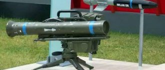
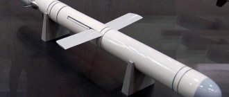
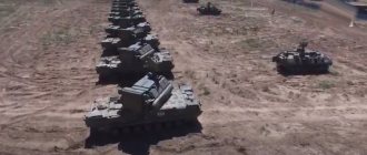
Regimental self-propelled anti-aircraft missile system "Strela-1"
The development of the complex began on August 25, 1960 in accordance with the Resolution of the Council of Ministers of the USSR. The deadline for submitting proposals for further work (taking into account firing tests of an experimental batch of missile samples) is the third quarter of 1962. The resolution provided for the development of a light portable anti-aircraft missile system, consisting of two parts weighing no more than 10-15 kilograms each. The complex was designed to destroy air targets flying at altitudes from 50-100 meters to 1-1.5 kilometers at speeds of up to 250 meters per second, at a distance of up to 2 thousand meters. The lead developer of the complex as a whole and the anti-aircraft guided missile is OKB-16 GKOT (later transformed into the Precision Engineering Design Bureau (KBTM) of the Ministry of Defense Industry). This organization during the war years and the first post-war years under the leadership of chief designer Nudelman A.E. has achieved significant success in the development of anti-aircraft naval and aviation small-caliber cannon weapons. By the beginning of the 1960s. The design bureau has already completed the development of a complex anti-tank system equipped with a Phalanx radio-controlled missile. When developing the Strela-1 (9K31) air defense system, unlike other short-range missile systems (such as the American Red Eye and Chaparral), it was decided to use a photocontrast head on the missile rather than an infrared (thermal) one homing. In those years, due to the low level of sensitivity of infrared homing heads, target identification in the forward hemisphere was not ensured, and therefore firing at enemy aircraft was carried out only “in pursuit”, mainly after they had completed combat missions. In such tactical conditions, there was a high probability of the destruction of anti-aircraft missile systems even before they launched missiles. At the same time, the use of a photo-contrast homing head made it possible to destroy a target on a collision course.
The main organization developing the optical seeker for the anti-aircraft guided missile was determined to be TsKB-589 GKOT, the chief designer was V.A. Khrustalev. Subsequently, TsKB-589 was transformed into the TsKB "Geophysics" MOP, work on the homing head for the Strela guided missile was headed by D.M. Khorol.
Already in 1961, the first ballistic missile launches were carried out, and by the middle of the next year, telemetric and program launches were carried out. These launches confirmed the possibility of creating a complex that largely meets the approved requirements of the Customer - the Main Missile and Artillery Directorate of the Ministry of Defense.
In accordance with the same Resolution, the development of another portable anti-aircraft missile system, Strela-2, was carried out. The overall dimensions and weight of this missile system were less than that of the Strela-1 air defense system. Initially, the development of Strela-1 to some extent supported the work on Strela-2, which were associated with a greater degree of technical support. risk. After resolving the fundamental issues related to the development of the Strela-2 air defense system, the question arose about the further fate of the Strela-1 complex, which had practically the same performance characteristics. For the expedient use of the Strela-1 air defense system among the troops, the leadership of the State Defense Committee turned to the Government and the Customer with a proposal to set higher requirements for this missile system in terms of maximum reach in height (3.5 thousand m) and destruction range (5 thousand. m), abandoning the portable design of the missile system, moving to placement on a vehicle chassis. At the same time, it was planned to increase the mass of the rocket to 25 kg (from 15 kg), diameter - to 120 mm (from 100 mm), length - to 1.8 m (from 1.25 m).
By this time, the customer had decided on the concept of combat use of the Strela-1 and Strela-2 anti-aircraft missile systems. The Strela-2 portable complex is used in the battalion air defense unit, and the Strela-1 self-propelled air defense system is used in the regimental air defense unit, in addition to the Shilka anti-aircraft self-propelled gun, the firing range of which (2500 m) does not ensure the destruction of helicopters and aircraft the enemy to the line of their launching guided missiles at targets and positions of a tank (motorized rifle) regiment (from 4000 to 5000 m). Thus, the Strela 1 anti-aircraft missile system, which has an extended destruction zone, fit perfectly into the military air defense system being developed. In this regard, the industry supported the relevant proposals.
Somewhat later, the BRDM-2 armored reconnaissance road vehicle was used as a base for the Strela-1 self-propelled anti-aircraft missile system.
It was envisaged that the anti-aircraft missile system, which has expanded combat capabilities, would be presented for joint testing in the third quarter of 1964. But due to difficulties with developing the homing head, work dragged on until 1967.
State tests of a prototype of the Strela-1 air defense system were carried out in 1968 at the Donguz test site (head of the test site Finogenov M.I.) under the leadership of a commission headed by Andersen Yu.A. The complex was adopted by the Decree of the Central Committee of the CPSU and the Council of Ministers of the USSR dated April 25, 1968.
Serial production of the 9A31 combat vehicle of the Strela-1 anti-aircraft missile system was launched at the Saratov MOP Aggregate Plant, and 9M31 missiles at the Kovrov Mechanical Plant MOP.
Nudelman A.E., Shkolikov V.I., Terentyev G.S., Paperny B.G. and others for the development of the Strela-1 air defense system were awarded the USSR State Prize.
The Strela-1 air defense system, as part of a platoon (4 combat vehicles), was part of an anti-aircraft missile and artillery battery (Shilka - Strela-1) of a tank (motorized rifle) regiment.
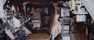
The 9A31 combat vehicle of the Strela-1 complex was equipped with a launcher with 4 anti-aircraft guided missiles placed on it, located in transport and launch containers, optical aiming and detection means, missile launch equipment and communications equipment.
The complex could fire at helicopters and airplanes flying at altitudes of 50-3000 meters at speeds of up to 220 m/s on a catch-up course and up to 310 m/s on a head-on course with course parameters up to 3 thousand m, as well as at drifting balloons and on hovering helicopters. The capabilities of the photo-contrast homing head made it possible to fire only at visually visible targets located against the background of continuous clouds or clear skies, at angles between the directions of the sun and the target of more than 20 degrees, and when the angular excess of the target's line of sight above the visible horizon was more than 2 degrees. Dependence on the background situation, weather conditions and target illumination limited the combat use of the Strela-1 anti-aircraft complex. But, average statistical estimates of this dependence, taking into account the capabilities of enemy aviation, basically in the same conditions, and later the practical use of air defense systems in exercises and during military conflicts showed that the Strela-1 complex could be used quite often and effectively ( according to military-economic indicators).
To reduce the cost and increase the reliability of the combat vehicle, the launcher was aimed at the target through the muscular efforts of the operator. Using a system of lever-parallelogram devices, the operator moved the interconnected launch frame with missiles, a rough sight and the lens of the optical sighting device to the required elevation angle (from -5 to +80 degrees) with his hands, and with his feet, using knee rests connected to the seat, he aimed the launcher in azimuth (while pushing off from a cone fixed to the floor of the vehicle). The front wall of the tower in the sector of 60 degrees in azimuth was made of bullet-resistant transparent glass. The launchers in the transport position were lowered to the roof of the vehicle.
Firing in motion was ensured by the almost complete natural balance of the swinging part, as well as by combining the center of gravity of the launcher with missiles with the point of intersection of the swing axes of the combat vehicle, thanks to the operator’s ability to reflect low-frequency vibrations of the body.
The 9M31 missile defense system featured a canard aerodynamic configuration. The missile was aimed at the target using a homing head using the proportional navigation method. The homing head converted the radiant energy flow from a contrasting target against the sky into an electrical signal, which contains data on the angle between the missile-target line of sight and the axis of the seeker coordinator, as well as on the angular velocity of the line of sight. The sensitive elements in the homing head were uncooled lead-sulfur photoresistors.
Behind the homing head, the steering gear of the aerodynamic triangular rudders, the control system equipment, the warhead and the optical fuse were successively placed. Behind them was a solid-fuel rocket engine; trapezoidal wings were attached to its tail section. The rocket used a dual-mode single-chamber solid-fuel rocket engine. The rocket at the launch site accelerated to a speed of 420 meters per second, which was maintained approximately constant during the march.
The missile's roll was not stabilized. The angular velocity of rotation relative to the longitudinal axis was limited by the use of rollerons - small rudders on the tail (wing), inside of which disks connected to the rudders were installed. The gyroscopic moment from the disks rotating at high speed turned the rolleron so that the roll rotation of the rocket was slowed down by the resulting aerodynamic force. A similar device was first used on the American-made Sidewinder air-to-air missile and on the K-13, its Soviet copy, launched into mass production simultaneously with the start of development of the Strela-1 air defense system. But on these rockets, the rollers, which have small blades around their circumference, spun long before launch under the influence of the air flow that flowed around the carrier aircraft. In order to timely spin the rollers of an anti-aircraft guided missile, the designers of the Strela-1 complex used a simple and elegant device. A cable was wound around the rolleron, secured to the transport launch container with the free end. When starting, the roller wheels were spun by a cable according to a pattern that was similar to that used to start outboard motors.
A contact magnetoelectric sensor in the event of a direct hit or a non-contact electro-optical sensor in the event of a flight near the target activated the PIM (safety actuator mechanism) to detonate the warhead of the guided missile. If there was a big miss, the PIM was removed from the combat position after 13-16 seconds and could not detonate the warhead. The anti-aircraft guided missile deformed when falling to the ground rather than exploding, without causing significant damage to its troops.
The diameter of the rocket was 120 mm, length - 1.8 m, wingspan - 360 mm.
The 9M31 missile, along with the missile of the Strela-2 complex, was one of the first domestic anti-aircraft guided missiles, which was stored, transported in a transport and launch container and launched directly from it. The dust- and splash-proof TPK 9YA23, which protected the missiles from mechanical damage, was attached to the launcher frame using yokes.
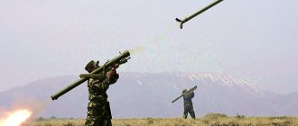
The combat operation of the Strela-1 anti-aircraft missile system was carried out as follows. When visually independently detecting a target or upon receiving target designation, the gunner-operator points the launcher with loaded guided missiles at the target, using an optical sight to increase accuracy. At the same time, the power supply on board the first guided missile is turned on (after 5 seconds, the second one) and the covers of the TPK are opened. Having heard the sound signal that the homing head has captured the target and visually assessed the moment of entry into the target launch zone, the operator presses the “Start” button to launch the missile. While the missile is moving through the container, the power supply cable for the guided missiles is cut off, and the first stage of protection in the PIM is removed. The fire was carried out according to the “fire and forget” principle.
During the tests, the probability of being hit by one guided missile when fired towards a target moving at an altitude of 50 m at a speed of 200 m/s was determined. They were: for a bomber - 0.15..0.64, for a fighter - 0.1..0.6. With an increase in altitude to 1 km and speed to 300 m/s, the probabilities for a bomber were 0.15..0.52 and for a fighter - 0.1..0.42.
The probability of hitting targets moving at a speed of 200 m/s when firing in pursuit ranged from 0.52 to 0.65, and at a speed of 300 m/s – from 0.47 to 0.49.
In accordance with the recommendations of the State Commission for Testing from 1968 to 1970. the complex was modernized. A passive direction finder developed by the Leningrad Research Institute “Vector” of the Ministry of Radio Industry was introduced into the anti-aircraft missile system. This radio direction finder provided target detection with on-board radio equipment turned on, its tracking and entry into the field of view of the optical sight. It also provided for the possibility of target designation based on information from an anti-aircraft missile system equipped with a passive direction finder to other simplified Strela-1 complexes (without a direction finder).
Thanks to the improvement, the missiles have reduced the near limit of the air defense system's engagement zone, increased the homing accuracy and the likelihood of hitting targets flying at low altitudes.
We have also developed a testing machine that allows us to monitor the operation of the combat assets of the Strela-1 anti-aircraft missile system, taking into account the changes introduced during the modernization.
State tests of the modernized Strela-1M air defense system were carried out at the Donguz test site in May-July 1969 under the leadership of a commission headed by V.F. Voropaev. The Strela-1M anti-aircraft missile system was adopted by the ground forces' air defense forces in December 1970.
According to the test results, the air defense system could ensure the destruction of helicopters and aircraft flying at altitudes of 30-3500 m, at speeds of up to 310 m/s, with heading parameters of up to 3.5 km, and maneuvering with overloads of up to 3 units at ranges from 0.5... 1.6 to 4.2 km.
In the modernized complex, compared to the Strela-1 complex, the near boundary of the zone was reduced by 400-600 meters, and the lower zone - to 30 meters. The probability of hitting a non-maneuvering target with uniform backgrounds increased and at altitudes up to 50 meters at a target speed of 200 m/s when firing towards it was 0.15-0.68 for a bomber and 0.1-0.6 for a fighter. These indicators at a speed of 300 m/s at an altitude of 1 km were 0.15-0.54 and 0.1-0.7, respectively, and when shooting in pursuit - 0.58-0.66 and 0.52-0, 72.
The combat operation of the Strela-1M anti-aircraft missile system had some differences from the autonomous operation of the Strela-1 air defense system. All platoon complexes on the ground were oriented in the same coordinate system for the Strela-1 - Shilka anti-aircraft missile and artillery battery. Radio communication was maintained between the machines. The commander of the anti-aircraft missile system monitored the radio technical situation in the radio direction finder's coverage area using sound and light all-round indicators. When sound and light signals appeared, the commander assessed the state ownership of the target. After deciding whether the detected signal belonged to the radar of an enemy aircraft, the commander, using internal communication, informed the battery commander, the operator of his vehicle and the rest of the platoon’s combat vehicles in the direction to the target. The battery commander carried out target distribution between the vehicles of the ZSU and SAM platoons. The operator, having received data about the target, turned on the precision direction finding system and deployed the launcher towards the target. Having convinced himself that the received signal belonged to enemy assets, he followed the target with the help of synchronous signals in the headset and on the light indicator until it entered the field of the optical sighting device. After this, the operator aimed the launcher with missiles at the target. Then the launch equipment was switched to “Automatic” mode. The operator, when the targets approached the launch zone, turned on the “Board” button and supplied voltage to the guided missile. The rocket was launched. The operating modes “Forward” and “Back” provided for in the air defense system allowed the operator, depending on the position relative to the target complex, its speed and type, to fire after or towards. So, for example, when launching in pursuit of all types of targets, and when launching towards low-speed targets (helicopters), the “Back” mode was set.
The battery was controlled by the regimental air defense chief through automated launchers - PU-12 (PU-12M) - which he and the battery commander had. Orders, commands, as well as target designation data to the Strela-1 complexes from PU-12(M), which was a battery command post, were transmitted via communication channels formed using radio stations available on these control and destruction equipment.
The Strela-1 and Strela-1M air defense systems were exported from the USSR to other countries quite widely. SAM systems were supplied to Yugoslavia, Warsaw Pact member countries, Asia (Vietnam, India, Iraq, North Yemen, Syria), Africa (Angola, Algeria, Benin, Guinea, Egypt, Guinea-Bissau, Madagascar, Libya, Mali, Mozambique , Mauritania) and Latin America (Nicaragua, Cuba). Used by these states, the complexes have repeatedly confirmed their ease of operation and fairly high efficiency during shooting exercises and military conflicts.
For the first time, Strela-1 anti-aircraft missile systems were used in 1982 in combat operations in Southern Lebanon in the Bekaa Valley. In December of the following year, these complexes shot down American aircraft A-7E and A-6E (possibly the A-7E was hit by a portable complex of the Strela-2 family). Several Strela-1 air defense systems were captured in the south of Angola by South African invaders in 1983.
Main characteristics of anti-aircraft missile systems of the Strela-1 type: Name: Strela-1/Strela-1M; 1. Damage zone: - in range - 1..4.2 km/0.5..4.2 km; — in height – 0.05..3 km/0.03.. 3.5 km; — by parameter — up to 3 km/up to 3.5 km; 2. The probability of hitting a fighter with one guided missile is 0.1..0.6/0.1..0.7; 3. The maximum speed of the target hit towards/after is 310/220 m/s; 4. Reaction time – 8.5 s; 5. Guided missile flight speed – 420 m/s; 6. Rocket mass - 30 kg / 30.5 kg; 7. Weight of the warhead – 3 kg; 8. The number of anti-aircraft guided missiles on a combat vehicle is 4; 9. Year of adoption – 1968/1970.
History of the creation of the Strela air defense system
On July 24, 1969, in accordance with the resolution of the Council of Ministers of the USSR and the Central Committee of the CPSU, the development of the 9K35 Strela-10SV air defense system began. The development of the complex took place at the Precision Engineering Design Bureau through the consistent improvement and modification of the 9K31 Strela-1 air defense system.
Between January 1973 and May 1974, the Strela-10SV anti-aircraft missile system was tested at the test site. During the tests, they had to decide on the feasibility of entering this complex into service. According to the developers and representatives of the GRAU, this air defense system fully complied with the requirements placed on it. But the opinions of the representatives of the testing site and the chairman were different. Claims were made against the missile defense system in terms of the insufficient probability of hitting a target with one missile or when using photocontrast and infrared channels. There were doubts about the reliability of the combat vehicle and 9M37 missiles. There were also comments about the convenience of combat crews and the placement of equipment. As a result, it was decided that the 9K35 air defense system can enter service only after all the comments have been eliminated. All the shortcomings were eliminated by 1976, when the complex, after repeated tests, entered service.
Notes[ | ]
- Strela-2 (11F610) (unspecified)
. Gunter's Space Page. Access date: January 10, 2015. - Strela-1M (11F625) (unspecified)
. Gunter's Space Page. Access date: January 10, 2015. - ↑ 1 2
Strela-1M
(unspecified)
. Encyclopedia Astronautica. Retrieved January 10, 2015. Archived August 5, 2014. - Strela-2M (11F610) (unspecified)
. Gunter's Space Page. Access date: January 10, 2015. - Strela-3 (17F13) (unspecified)
. Gunter's Space Page. Access date: January 10, 2015. - "Rokot" launched three satellites // Cosmonautics News: magazine. - FSUE TsNIIMash, 2010. - Issue. 334.
Links
Air Force and Air Defense Short range (10 to 50 km) S-25 "Berkut" • S-75 "Dvina" • S-125 "Neva"/"Pechora" Medium range (from 50 to 200 km) "Dal" • S-300P • S-300PT • S-300PS •
VityazLong range (> 200 km) S-200 • S-300PM • S-400 “Triumph/Triumfator” • S-500/S-1000 Memory of the Russian Ground Forces ZO ZU-23-2 • S-60 • KS-19 • KS-30 • KM-52 ZSU ZSU-23-4 Shilka • Object 530 •
ZSU-37-2 “Yenisei”
• ZSU-57-2 • 2K22 “Tunguska”SAM 9K31 "Strela-1» • 9K35 “Strela-10” • "MD-PS" •
“Pine”
• 9K33 “Osa” • 9K330 “Thor”Short range (15 to 30 km) 2K12 "Cube" Medium range (from 30 to 100 km) 2K11 “Krug” • 9K37 “Buk” • 9K37M1 “Buk-M1” • 9K37M1-2 “Buk-M1-2” • 9K317 "Buk-M2" •
"Buk-M3"Long range (> 100 km) 9K81 S-300V “Antey-300” • 9K81M S-300VM “Antey-2500” ZU of the Russian Navy SAM "Strela-M" • 3M47 "Gibka" • M-4 "Osa-M" • 3K95 "Dagger/Blade" • Short range (15 to 40 km) M-1 "Volna" • M-2 "Volkhov-M" • M-11 "Storm" • M-22 "Hurricane" • 3S90E.1 "Calm-1" • "Tornado" Collective Defense (> 40 km) S-300F “Fort” • S-300FM “Fort-M” • “Redut” Command posts, controls, miscellaneous Ground Forces KSA "Barnaul-T" • UBKP "Rangir" • UBKP "Ranzhir-M" • "Senezh" • "Baikal-1" • KUZA-1 • 9S44 "Crab" K-1 • "Polyana-D1" • "Polyana- D4" • KP 9S470 (9K37 "Buk") • KP 9S457 (ZRS S-300V) Navy "Fort" * - produced only for export. Italic Promising, experimental, or samples that did not go into mass production were identified
T-44 · T-54 · T-55 · Object 416
·
Object 141
·
Object 139
·
Object 907
·
Object 140
·
Object 142
·
Object 430
·
Object 435
·
Object 167
· T-62 · T-62A ·
Object 920
· T-64
[/td]Medium tanks Heavy tanks IS-3 IS-4 IS-7 · T-10 ·
Object 266
·
Object 277
·
Object 278
·
Object 279
·
Object 770Missile tanks IT-1 · Item 64992 ·
Object 170
·
Object 431
·
Object 757
·
Object 772
·
Object 282
·
Object 906B
·
Object 775
·
Object 287
·
Object 780Flamethrower tanks OT-54 · Object 483 TO-55
BMPT Object 781 ·
Object 782
·
Object 787
· Object 199 "Frame"* ·
BMPT-72Main battle tanks T-62B · T-64A · T-64BV ·
Object 476
·
Object 172
·
Object 172-2M
· T-72 · T-72A · T-72B · T-72BA · T-72B3 · T-74 ·
T
-80 ·
T- 80A
·
Object 478
·
Object 785
·
Object 187
·
Object 477
·
Object 292
· T-80U · T-80UD · T-90 ·
T-90AM
·
Object 640
·
Object 195
·
T-14 (based on TSUP "Armata")ATGM combat vehicles 2P27 "Bumblebee" · 2P32 "Phalanx" · 9P19 "Eye" · 9P110 "Malyutka" · 9P122 "Malyutka-M" · 9P124 "Phalanga-M" · 9P133 "Malyutka-P" · 9P137 "Flute" · 9P148 "Konkurs" · 9P149 "Sturm-S" · 9P157 "Chrysanthemum-S" · 9P161 "Kornet-S" · 9P162 "Kornet-T"
Combat reconnaissance vehicles BRDM-1 Object 760 (“hover tank”) ·
BRDM-VPK
·
BRDM-VPS
·
Object 8M-906
· BRDM-2 · BRDM-3 · BRM-1K ·
BRM-2
· BRM-3K ·
BKM Airborne Forces "Vydra"
·
Patrol-AFlamethrower combat vehicles BMO-1 · BMO-T Armored personnel carriers K-75 · BTR-40 ·
BTR-112
·
K-78
· BTR-152 ·
ZIS-153
· BTR-50 ·
BTR-E152V
·
ZIL-153
·
GT-L
·
GT-LB
·
Object 1015
· BTR-60 · MT-
D
· BTR-70 · BTR-80 · BMM-80 · BTR-82 · BTR-90
·
BTR-T
· BTR-MD “Rakushka” ·
BMM-D
“ Boomerang " DT
-3PB
"
KrymskArmored vehicles Ural-4320-09-31 Ural-E4320D-31 Ural-E5323D GAZ-39344 ·
"Warrior"
·
"Bear"
·
Ural-6320
· "Typhoon" · ("Typhoon-U" ·
Ural-63099
· "Typhoon-K" ·
KAMAZ-63969
) · "Vodnik" · "Shot" · "Tiger" ·
"Wolf"
·
"Scorpion LTA"
·
"Bulat"
·
"Highlander-K"
·
"Federal-M" ("Stargazer")
·
"Scorpion LSA-B"ASU-76 ·
K-73
· SU-100P ·
SU-100M
· ASU-57 ·
BSU-11-57F
·
Object 574
· ASU-85 · SU-152
"Taran"
·
2S14 "Sting-S"
·
2S15 "Norov"
·
" Hermes"
· 2S25 "Sprut-SD" ·
2S28 "Sprut-K"
[/td]Anti-tank Self-propelled howitzers and mortars SU-152G ·
2A3 "Kondensator-2P"
·
2B1 "Oka"
·
Self-propelled guns with D-80
·
Self-propelled guns with D-80S
·
Self-propelled guns with D-80-2
· 2С1 "Gvozdika" ·
2С2 "Violet"
· 2С3 "Acacia" · 2С4 " Tulip" · 2S5 "Gyacinth-S" · 2S7 "Peony" ·
2S8 "Astra"
· 2S9 "Nona-S" ·
2S11 "Gyacinth-SK"
· 2S12B "Tundzha-Sani"* ·
2S17 "Nona-SV"
·
2S17 -2 "Nona-SV"
·
2S18 "Pat-S"
·
Object 327
· 2S19 "Msta-S" ·
2S21 "Msta-K"
·
2S22 "Flask-3"
·
"Compartment"
· 2S23 "Nona-SVK" · 2S24 "Virgo" ·
2S26 "Pat-K"
·
2S27 "Reef"
·
"Crimping"
·
2S30 "Iset"
· 2S31 "Vena" ·
2S33 "Msta-SM"
· 2S34 "Khosta" ·
2S35 "Coalition-SV"
·
Koalitsiya-SV-KSh
2S36
"Zauralets-D"Coastal A-222 "Bereg" BM MLRS and OTRK TZM 9T451 "Grad-1" · TZM "Grad-VD" · TZM-T “Solntsepek”
SPU SPU 2P2 "Mars" · SPU 2P4 "Filin" · SPU 2P5 "Korshun" · SPU 2P16 "Luna" ZSU-37-2 "Yenisei" ·
Object 130
[/td]37 mm 30 mm 2S6 "Tunguska" · 96K6 "Pantsir-S1" · ZPRK "Roman" ·
ZSU TKB-841 "Pantsir-S1-O"23 mm ZSU-23-4 "Shilka" BM air defense systems and air defense systems Strela-10 BM 9A35 SAM 9K35 "Strela-10-SV" Pine BM SAM "Sosna" Wasp BM 9A33B SAM 9K33 “Osa” Thor BM 9A330 SAM 9K330 “Tor” Cube SURN 1S91 SAM 2K12 "Kub" · SPU 2P25 SAM 2K12 "Kub" · SOU 9A38 SAM 2K12M4 "Kub-M4" Beech KP 9S470 SAM 9K37 "Buk" · SOC 9S18 SAM 9K37 "Buk" · SOU 9A310 SAM 9K37 "Buk" · PZU 9A39 SAM 9K37 "Buk" · RPN 9S36 SAM 9K317 "Buk-M2" Circle SOC 1S12 SAM 2K11 "Krug" · SNR 1S32 SAM 2K11 "Krug" · SPU 2P24 SAM 2K11 "Krug" S-300V KP 9S457 air defense system 9K81 "Antey-300" · radar 9S15 air defense system 9K81 "Antey-300" · radar 9S19 air defense system 9K81 "Antey-300" · MSNR 9С32 air defense system 9K81 "Antey-300" · PU 9А82 air defense system 9K81 "Antey-300" · PU 9A83 ZRS 9K81 "Antey-300" · ROM 9A84 ZRS 9K81 "Antey-300" · ROM 9A85 ZRS 9K81 "Antey-300" Cranes KT-15 · SPK-5 · SPK-12G BIS UR-67 · UR-77 · UR-88 ·
UR-93
· UR-07 · BMR-1 · BMR-2 · BMR-3 · BMR-3MIMR IMR-1 IMR-2 IMR-3 IMR-3M "Klin-1" AZM ·
ADZM "Vostorg-2"
· BAT-M · BAT-2RHM BRDM-2РХБ · РХМ · РХМ-2 · RKhM-3 · РХМ-4 · РХМ-5 · РХМ-6 · РХМ-7
BREM BREM-1 BREM-2 BREM-3 BREM-80U BREM-L BREM-D BREM-K RM-G
MTU MTU · MTU-20 · MTU-55 · MTU-72 · MTU-90 ICC MTP-1 · MTP-2 · MTP-3 · MTP-A5 Other SPU-117 · IRM · IPR · VTS · KDHR-1N · BTZ-3 · LKM-1 · LKM-3 · P-256G · RPM-2 · KhTV-64 · SPM
PRP and PPU PRP-3 "Val" · PRP-4 "Nard" · PRP-4M "Deuterium" · PPRU-1 "Gadfly-M-SV" · 9S482 (PU-12) · 9S482М6 (PU-12М6) · 9S737 "Rank" · 9S737M "Rangir-M" · 15Y56 (MBP) · "Palantin-P" KSAUO 1B13 1B14 1B15 1B16 Object 940 · 1В18 "Klen-1" · 1В19 "Klen-2" · 1В117 · 1В118 · 1В119 "Rheostat" · 1В152 · 1В157 · 1В21 · 1В22 · 1В23 · 1В24 · 1В25 · 1В31
Radar 1RL232 “Leopard” · SNAR-15 "Selenite" · 1RL239 “Lynx” · 1Л219 “Zoo”
electronic warfare 1L21 (SPR-1) 1L29 (SPR-2) 1K11 "Stiletto" ·
“Sanguine”
·
1K17 “Compression”* - produced only for export; italics Promising, experimental, or samples that did not go into mass production were identified
Performance characteristics
This air defense system has performance characteristics that are characterized by high reaction speed and mobility. The time the projectile is ready to launch can vary from five to ten seconds, depending on the conditions under which the equipment is operated. Reception of target indications is carried out in 3-5 seconds. The distortion of azimuth data at a distance of 6 – 25 km from the object is – 1.5 degrees.
In addition, the Strela-10 air defense system has decent firing range characteristics, namely the maximum distance to the target with a probability of hitting the target up to 99.5 percent is 5 kilometers. In this case, the flight altitude varies from 25 to 3500 m. The speed of the rocket on a collision course is about 1500 km per hour, in pursuit - up to 1110 km per hour. Recognition of air targets occurs at a distance of up to 12 thousand meters.
Transferring the installation to a combat position from a marching position takes no more than 20 seconds. Full reload time (four missiles) varies between 2-3 minutes. It takes 3 minutes to wind down active weapons.
The total weight of the Strela-10 air defense system is 12.3 tons. At the same time, the vehicle develops a floating speed of up to 6 km per hour, and on the ground up to 61.5 km per hour.
Modifications
Over the long period of service, the Strela-10 air defense system has been repeatedly modernized. The first of them was carried out in 1977. The 9K35M "Strela-10M" air defense system differed from the base model only in its homing head. Now the missile chose a target based on trajectory characteristics, and it was more difficult to mislead it with the help of heat traps.
The remaining characteristics of the 9K35 modification were similar to the base model. Tests of the new vehicle were carried out in 1978, a year later it was put into service.
9K35M2 "Strela-10M2". Work on the creation of this modification of the air defense missile system began at the initiative of the Ministry of Defense and the State Grain Administration. The complex was equipped with equipment for receiving target designation from the PU-12M battery command post and the command post of the air defense regiment commander. During the modernization, combat vehicles were equipped with floats for overcoming water obstacles with full ammunition and a machine gun. The complex was equipped with a new radio station. Testing of the new modification began in 1980, and in 1981 it was put into service.
9K35M3 "Strela-10M3". On April 1, 1983, another modernization of the complex began. The new modification was supposed to have higher noise immunity, a longer engagement range and ensure effective shooting at all categories of low-flying targets: helicopters, airplanes, cruise missiles and unmanned aerial vehicles.
Tests and modifications of the Strela-10M3 were carried out for several years, and in 1989 the complex was put into service.
"Strela-10M4". This is the first modification of the machine developed after the collapse of the Soviet Union. Its main feature is an improved anti-aircraft missile with a new thermal imaging system, target acquisition and tracking system.
"Strela-10T". A modification of the complex, developed in Belarus, based on the Strela-10M2 air defense system. The main feature of the Belarusian development is a new computing system, a GPS navigation complex and an optical-electronic system. The air defense system can be placed on a wheeled chassis.
For the Strela-10 complexes, a new anti-aircraft missile 9M333 was developed, which has a more advanced engine, a new seeker, autopilot, and warhead. The 9M333 missile defense system is placed in a special launch container. The homing head has not two, but three modes: infrared, photo-contrast and interference, which significantly increases the missile’s noise immunity. Another feature of the 9M333 is its warhead. It has a mass of five (and not three kg, as on the 9M37 missile defense system), which significantly increases the likelihood of hitting a target. The length and cross-section of the missile's striking elements were also increased. Its overall dimensions have also changed: the length has increased to 2.23 m. 9M333 can be used on any modification of the Strela-10 complex.
Car[edit]
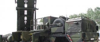
Each TEL carries four ready-to-launch missiles, but usually has no missiles to reload. Recharging is done manually and usually takes about 5 minutes. The missile transport boxes are lowered to reduce the overall height of the vehicle. The driver and commander have periscopes for viewing outside the vehicle when the hatches are closed.
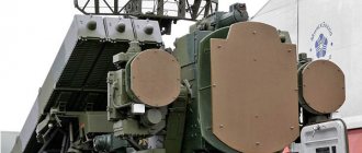
9K31 TEL with a "Flat Box" passive radar detection antenna array. Photo by GulfLINK.
Another important change to the BRDM-2 chassis, besides the new turret, is the removal of road wheels (which are presumably intended to improve off-road performance). The driver and commander have infrared vision systems. The vehicle has standard NBC (nuclear, biological and chemical) protection, including overpressure. The missiles are folded on the sides of the turret, which significantly reduces the height of the vehicle during flight. Each vehicle weighs approximately 7 tonnes (7.7 short tons) and is equipped with a 104 kW (140 hp) engine and a central tire pressure monitoring system.
Operators
- Angola Angola - 20 9K31, as of 2012[3]
- Algeria Algeria - about 20 9Q31, as of 2012[4]
- Armenia Armenia - 30 Strela-1, as of 2016[5]
- Bosnia and Herzegovina Bosnia and Herzegovina - 6 9K31, as of 2012[6]
- Egypt Egypt - 20 9K31, as of 2012[7]
- India India - 200 9K31, as of 2012[8]
- Yemen Yemen: Yemen Ground Forces - some 9K31, as of 2012[9]
- Yemen's air defense forces - a number of 9K31, as of 2012[9]
2083 days ]
Former operators
- USSR USSR - passed to the states formed after the collapse
- Russia Russia: Russian Ground Forces - 200 9K31, as of 2012[8]
- Russian Marine Corps - 50 9K31 and 9K35, as of 2012[19]
Combat use
The Strela-10 air defense system was exported and took part in several armed conflicts.
Strela-10 complexes were used by the Libyan army during the war with Chad. These air defense systems were actively used during the civil war in Angola. Anti-aircraft systems were in service with MPLA units, and they were also used by Cuban volunteers. In 1988, with the help of this complex, a Mirag-F-1AZ of the South African Air Force was shot down. During this conflict, air defense systems data were captured as trophies and studied by Western experts.
Iraqi forces used the Strela-10 air defense system during the Gulf War, but there is no information about the successful use of this weapon. This complex was also used during conflicts in the territory of the former Yugoslavia.
The Strela-10 air defense system is used in the conflict in eastern Ukraine by both sides, with separatists especially actively using it. 9K35 is very effective against unmanned aerial vehicles due to the presence of a photo-contrast guidance channel.
Characteristics
| Modification | "Strela-10M" |
| Width, mm | 2850 |
| Height, mm | 2220 |
| Length, mm | 6450 |
| Rocket type | 9M37, 9M37M |
| Damage height, m | 25 – 3000 |
| Damage range, m | 8000 – 5000 |
| Probability of hitting a target with one missile | 0,1 – 0,4 |
| Time to bring into combat position, s | 30 |
| Crew, people | 3 |
Software
The stands include Strela M1 software, developed for specific measurement tasks and also performing measurement process control functions.
Table 1
| Name BY | Identification tional Name BY | Software version number (identification number) | Digital software identifier (executable code checksum) | Algorithm calculations digital identifier BY |
| Strela M1 | Strela M1.exe | 2.0 | D8B0aB881c52 D46B30ebc7c13 B0FF 647 | MD5 |
The software and its environment are immutable, means for programming or changing metrologically significant functions
none.
The stand software protection corresponds to level “C” according to MI 3286-2010.
