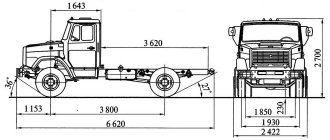
We produce several types of drive axles suitable for installation on various SUVs, including UAZ. All types of bridges have a track from 1450 to 2200 mm, the displacement of the main pair body varies. All axles can be equipped with disc brakes, locking systems (self-locking and forced), and tire inflation systems. Technical characteristics of axles for all-terrain vehicles: - The bridges are designed for wheels up to 1450 mm with a total weight of the all-terrain vehicle up to 3000 kg. -Spaces for springs and shock absorber mountings are manufactured at the request of the customer. -Weight from 150kg to 190kg depending on the version -On axles with tractor final drives: -The diameter of the driven shaft of the final drive is 50mm. - Portal capacity 114 mm.
______________________________________________________________________________
Prices are for a pair of axles as standard:
1,2,6 articles with drum brakes
3,4,5,7 articles with transmission disc brakes
If desired, add additional options:
-Self-locking differential in the axle 15,000 pcs .
-Forced locking (pneumatic, mechanical, hydraulic) in the bridge 30,000 pcs .
-Swap 30000 (3,4,5,7 option)
-Disc brakes in a circle of 50,000 for 2 axles (articles 3,4,5,7)
-Swap 50000 (1,2,6 articles)
-Disc brakes all around 30,000 for 2 axles axle (1,2,6 articles)
Features of the transmission of the BTR-80 armored personnel carrier
16>
The BTR-80 transmission is designed for:
transmission of torque from the engine crankshaft to the driving wheels of the machine and the water-jet propulsion;
changes in the vehicle speed on land and traction forces on the drive wheels in a wider range than can be achieved by changing the engine crankshaft speed;
ensuring smooth starting;
disconnecting the engine from the drive wheels of the vehicle when starting the engine and its operation while parked.
The technical characteristics of the transmission are disclosed in table 12.13.
The BTR-80 transmission (Fig. 12.44) includes :
clutch 12; gearbox 10; transfer case 22; cardan transmissions; bridges 17, 20, 24, 28; wheel reducers 4.
Rice. 12.44 BTR-82 transmission diagram:
1 – winch gearbox; 2 – front drive shaft of the winch drive; 3 – drive shaft of the wheel reducer drive; 4 – wheel reducer; 5 – rear drive shaft of the winch drive; 6 – drive shaft of the third axle; 7 – intermediate cardan shaft; 8 – front propeller shaft of the water-jet propulsion drive; 9 – intermediate support of the cardan transmission for the water-jet propulsion unit; 10 – gearbox; 11 – rear propeller shaft of the water-jet propulsion drive; 12 – clutch; 13 – water-jet propulsion gearbox; 14 – propeller shaft; 15 – engine; 16 – propeller; 17 – fourth bridge; 18 – rear propeller shaft of the fourth axle drive; 19 – intermediate support for the cardan transmission to the fourth axle; 20 – third bridge; 21 – front drive shaft of the fourth axle drive; 22 – transfer case; 23 – drive shaft of the second axle; 24 – second bridge; 25 – rear propeller shaft of the first axle drive; 26 – intermediate support of the cardan transmission to the first axle; 27 – front drive shaft of the first axle drive; 28 – first bridge.
Table 12.13
Technical characteristics of the BTR-80 transmission
| Type | Mechanical, stepped |
| Clutch: | Models 14 |
| Transmission: | mechanical, three-way, five-speed, with mechanical control drive, with synchronizers in II-III and IV-V gears |
| Transfer case: Type | Mechanical, interaxle, two-stage, with constant mesh gears, with differential torque distribution through a cardan transmission in two streams (on the 1st-3rd and 2nd-4th axles) and differential locking |
| Driveshafts: | Open, rigid, tubular shafts, joints on needle bearings, with end splines on flanges |
| Drive axles: quantity, pcs main gears differentials | Bevel, Spiral Tooth Lockable, Bevel Gear |
| Wheel reducers: quantity, pcs. gear ratio | Mechanical, single-stage, same type for all axes 4.33 |
Clutch mechanism
consists of driving parts, driven parts, a pressure device and a release mechanism. The clutch actuator is designed to control the clutch. The machine is equipped with a hydraulic drive with a pneumohydraulic booster, similar to the KamAZ-5350 vehicle.
When the clutch pedal is released, the spring pulls the pedal back until it stops against the bolt bracket, pulling the pusher in the same direction. In this case, the piston of the master cylinder, under the action of the return spring, is in the rearmost position, resting against the thrust bolt, and the reservoir of the cylinder body with the working fluid is connected through the compensation hole to the working cavity of the master cylinder. There is no pressure in the clutch drive, all actuators are in their original position. The clutch is engaged. When you press the pedal, the pusher moves the piston, compressing the return spring. As the piston moves, it displaces fluid under pressure from the main cylinder through a pipeline to the pneumatic-hydraulic booster. The pneumohydraulic amplifier comes into operation. The force created by it is transmitted to the clutch release mechanism.
Transmission
classic three-shaft with reverse gear block. It is similar to that used in the model 154 gearbox of the KamAZ-5350 vehicle. An oil cooler is additionally installed on it, which is a radiator and consists of a tray part and a finned body in which the oil and water lines are made. When driving on land, the cooler housing is cooled by a fan mounted on the propeller shaft of the fourth axle drive. When moving through water, the cooler housing is cooled by sea water.
Transfer case
serves to distribute torque from the gearbox to the drive axles, water-jet propulsion and winch, as well as to change the traction forces on the drive wheels.
The transfer case (Figure 12.45) consists of: crankcase; input shaft 29 with a block of gears for selecting upshift 16 and downshift 13, power take-off gear 31 for the propulsion unit and bearings; a power take-off shaft for a water-jet propulsion unit 22 with a gear 23, a coupling 26, a flange and bearings; drive shaft to the winch with clutch. flange and bearings; gears for upshifting 17 and downshifting 52; center differential with locking clutch; front intermediate shaft 65 with friction clutch, front drive gear 3, brake drum and bearings; rear intermediate shaft 32 with rear drive gear and bearings; drive shaft I bridge 63 with coupling, flange and bearings; secondary drive shaft of I and III bridges 53 with driven gear 57 and bearings; drive shaft II of bridge 50 with coupling and bearings; secondary drive shaft of bridges II and IV 40 with driven gear 44, brake drum and bearings; control drives; transfer case lubrication and cooling systems.
The transfer case housing is divided into upper 5 and lower 42 halves. The oil filler pipe with filter is also a breather. The transfer case locking devices ensure that downshifts are engaged and the center differential is locked only when the front axles are engaged (axles 1 and 2 are pluggable). To prevent damage when transmission elements are overloaded (with the differential locked), the transfer case has a friction clutch.
On the drive shaft of the transfer case there is a block of gears for selecting overdrive and downshift gears. The power take-off for the jet propulsion is mounted in the upper part of the transfer case from the input shaft through the power take-off gear and the power take-off for the winch is in the front part of the transfer case from the input shaft through the clutch. Torque from the drive shaft is transmitted through the center differential (serves to reduce the circulation of power in the vehicle transmission between the third and fourth axles) to the front and rear intermediate shafts, and through them to the drive shaft of axles I and III and the drive shaft of axles II and IV. Overdrive and downshift gears are mounted on the differential housing.
Rice. 12.45. Transfer case BTR-80:
1 – differential lock fork rod; 2 – rod nut; 3 – front drive gear; 4 – differential lock clutch; 5 – upper crankcase; 6 – gear shift fork rod; 7 – winch activation rod; 8 – winch drive engagement clutch; 9 – winch drive fork; 10 – top cover; 11 – left satellite box; 12 – satellite; 13 and 16 – input shaft gears; 14 – gear clutch; 15 – gear fork; 17 – overdrive gear; 18 – speedometer drive cover; 19 – driven gear of the speedometer drive; 20 – speedometer drive gear; 21 – oil pump; 22 – power take-off shaft for the propulsion unit; 23 – drive gear to the propeller; 24 – drive fork rod for driving the drive; 25 – fork for switching the drive to the mover; 26 – clutch for engaging the drive on the propulsion unit; 27 – drive shaft to the propeller; 28 – driveshaft mounting flange; 29 – input shaft; 30 – rear drive gear; 31 – drive gear for the propeller; 32 – rear intermediate shaft; 33 – oil washer; 34 – rear cover of the intermediate shaft; 35 – right satellite box; 40 – secondary drive shaft of bridges II and IV; 41 and 67 – brakes; 42 – lower crankcase; 43 and 51 – axle gears; 44 – driven gear; 45 – coupling bolt; 46 – power fork for bridge II; 47 – clutch for axle II; 48 – housing for the activation mechanism of the II bridge; 49 – rod of the switching fork of the II bridge; 50 – drive shaft of the II bridge; 52 – reduction gear; 53 – secondary drive shaft of axles I and III; 54 – hub of the inner clutch drum; 55 – clutch drive drum; 56 – clutch driven drum; 57 – driven gear; 58 – power fork of the 1st bridge; 59 – ball; 60 – housing for the activation mechanism of the first bridge; 61 – rod of the switching fork of the first bridge; 62 – rollers; 63 – drive shaft of the first bridge; 64 – clutch for 1st axle; 65 – front intermediate shaft; 66 – flange; 68 – winch drive shaft; 69 – winch drive drive sprocket
To increase cross-country ability and prevent wheel slipping when driving over rough terrain, the center differential lock is also activated simultaneously with the front axles being engaged. Bridges III and IV are always on.
A limiting torque clutch is installed on the front intermediate shaft. The driving and driven friction disks are installed on the gear rims of the driving and driven clutch drums and are clamped between the thrust and pressure disks by the force of fourteen springs. The clutch is designed to prevent overloading of cardan shafts, drive axles and wheel gears when the differential in the transfer case is locked. The friction clutch is designed to transmit a certain torque, therefore, when one of the pairs of drive axles (first and third or second and fourth) is overloaded, the friction discs slip and the center differential is simultaneously activated.
Clutches for engaging the front axles are installed on the front splined ends of the secondary shafts. The splined shank of the rear output shaft (goes to the rear axle) serves as a support for the parking brake drum.
The transfer case lubrication and cooling system is designed to lubricate the transfer case gears, bearing units and shafts, as well as to reduce the temperature of all parts by cooling the circulating oil. The system includes: an oil pump, an oil tank, two oil cooling radiators, pipelines and a warning light for system health.
The oil pump is attached to the front wall of the transfer case housing. The pump is two-section, gear. Each section has a pressure reducing valve. The outer section is connected by a tube to the bearing cover of the rear intermediate shaft, and the inner section is connected by hoses to the oil cooler and then to the cover of the drive mechanism for the water-jet propulsion. The oil pump is driven from the driven power take-off shaft to the jet propulsion unit.
The oil tank is installed on the right side of the transfer case. An oil receiver with a strainer is mounted on the inside of the tank lid. The oil tank is connected by a hose to the transfer case housing through pipes, and through a hose and tube to the RK oil pump.
Oil coolers serve to cool the transfer case oil. Oil radiators are mounted on the radiator of the cooling system.
To monitor the operation of the lubrication system, a sensor indicating the presence of pressure in the system is installed. The warning light is located on the driver's instrument panel. The sensor is triggered when the pressure in the discharge line drops below 0.4...0.6 kgf/cm2.
The lubrication and cooling system works as follows.
The oil pump supplies oil to the line only when the gear in the gearbox is engaged (for forward movement) and does not supply oil when reverse gear is engaged, as well as when the gearbox lever is in neutral position. The pump performance increases with increasing engine speed and when the higher gears in the gearbox are engaged. The oil pump sucks oil through an oil receiver with a strainer installed inside the tank. Oil from the internal section of the pump is supplied to the oil cooler. From the radiator, oil enters the transfer case housing onto the rotating power take-off gears of the jet propulsion unit, lubricating their ring gears and the bearings of the power take-off shaft and the transfer box drive shaft. At the same time, oil enters the crankcase of the drive activation mechanism for the water-jet propulsion unit and through the bearing into the transfer case housing. In this case, the parts of the mechanism for turning on the water-jet propulsion are lubricated by splashing. The outer section of the pump supplies oil to the rear cover to lubricate the differential parts. The oil drains from the transfer case housing into the reservoir.
Transfer case control drives include:
drive for engaging the front axles and locking the center differential;
gear shift drive;
drive for turning on the power take-off to the winch.
Cardan transmissions
designed to transmit torque from the engine to wheel gearboxes, water-jet propulsion and to the winch.
Cardan transmissions (Fig. 12.44) consist of nineteen shafts connecting:
gearbox with transfer case – intermediate cardan shaft 7;
transfer case with drive axles - six cardan shafts 6, 18, 21, 23, 25, 27 and two intermediate supports (transmissions to the front 26 and rear 19 axles);
drive axles with wheel reducers – eight cardan shafts 3;
transfer case with winch - two cardan shafts 2, 5 and an intermediate support;
transfer case with water-jet propulsion - two cardan shafts 8, 11 and an intermediate support 9.
All cardan shafts are equipped with swivel joints on needle bearings and telescopic spline joints (four types of cardan shafts). Cardan joints consist of forks and flanges connected to each other by crosspieces (the design is similar to the cardan shafts of the KamAZ-5350 car).
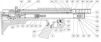
Rice. 12.46. Drive axle gearbox:
1 – long axle shaft; 2 – casing; 3 – sealing ring; 4 – filler (control) hole plug; 5 – driven gear; 6 – differential; 7 – cover with a locking mechanism; 8 – crankcase; 9 – short semi-axis; 10 – adapter ring; 11 – drive gear; 12 – bearing coupling; 13 – adjusting shims; 14 – bracket; 15 – flange; 16 – oil removal ring; 17 – adjusting nut; 18 – locking clutch; 19 – locking fork.
Bridges
designed to increase and transmit torque from the transfer case to the wheel gearboxes.
The machine is equipped with four drive axles with fully balanced axle shafts and cam limited-slip differentials.
Each bridge (Figure 12.46) is a hollow beam, inside which the main gear, differential 6 and axle shafts 1 and 9 are located. The main gear consists of a pair of bevel gears 5 and 11 with spiral teeth. Differential 6 cam, double-row, with radial arrangement of crackers, increased friction. It provides the ability to rotate the drive wheels at different speeds and increases the vehicle's maneuverability due to a more rational redistribution of torque on the slipping and non-slipping wheels.
Wheel reducers
designed to increase and transmit torque from drive axles to the wheels.
The gearbox (Figure 12.47) consists of: a drive shaft with a drive gear 3 and a drive flange 6; driven gear 28; wheel hub with brake drum 30.
The non-steer wheel gearbox is attached to the upper and lower suspension arms using connecting axles. The wheel reducer of a steered wheel differs from the wheel reducer of a non-steered wheel by the presence of a steering knuckle housing, which allows the wheel to rotate on king pins.
Rice. 12.47. Wheel reducer:
1 – rotary square; 2 – wheel tap; 3 – drive gear; 4 – bearing cover with seals; 5 and 15 – adjusting shims; 6 – flange; 7 – protective cap; 8 – seal of the upper king pin; 9 – nut of the upper king pin; 10 – upper kingpin; 11 – cover; 12 – liner; 13 – cardan shaft; 14 – tension screw; 16 – lock washer; 17 – bushing; 18 – suspension connecting axis; 19 – suspension arm; 20 – seal holder; 21 – bearing; 22 – steering knuckle body; 23 – lower king pin; 24 – grease fitting; 25 – plug; 26 – drain plug; 27 – crankcase; 28 – driven gear; 29 – conical split bushing; 30 – brake drum; 31 – brake mechanism; 32 – seal bearing; 33 – cuff; 34 – thrust bearing; 35 – receiving rod; 36 – air supply seal; 37 – cover; 38 – cotter pin wire; 39 – nut; 40 – hatch cover; 41 – brake drum cover; 42 – brake system pipe; 43 – fitting; 44 – air system tube; 45 – bushing; 46 – sealing ring.
The wheel hub is cast integrally with the brake drum and is attached to the driven gear on studs. The air supply to the tires is carried out through channels to the axle and receiving rod, a tube and bushing, an adapter fitting and a tube to the wheel valve.
Movement on water
is ensured by the operation of a single-stage water-jet propulsion unit with a four-blade impeller with a diameter of 425 mm. When moving on land, the exit window of the water cannon is closed by an armored flap. When moving through water, closing the damper directs water into the reverse channels. The maximum speed afloat is at least 9 km/h. The afloat cruising range at average engine operating conditions (1800-2200) is 12 hours.
16>
Date added: 2021-05-28; views: 966; ORDER A WORK WRITING
Find out more:
Serial production of BTR-60
Production of the BTR-60 was put on the assembly line in 1960. Although it was initially planned to produce military equipment of this model at several enterprises, in the end only the Gorky Automobile Plant remained the only manufacturer in the USSR. After some time, the armored personnel carrier underwent modernization:
- Night vision devices were installed;
- The crew commander received a panoramic type viewing device;
- The combat vehicle received an armored roof, which completely covered the armored personnel carrier.
Initially, it was not planned to make completely enclosed combat vehicles, but a military operation in Hungary in 1956 showed that in street battles, armored personnel carriers without a roof suffered huge losses from grenades and Molotov cocktails, which were thrown at them by rebels from the upper floors of buildings.
The second reason for the appearance of completely closed armored personnel carriers was the development of nuclear technology. Since nuclear war seemed quite likely at that time, motorized riflemen could not operate in conditions of radioactive contamination, so they could fire from under the armor. Although this limited the capabilities of the infantry, the advantages in protecting closed vehicles were obvious, so it was decided to completely switch to the production of closed vehicles.
History of creation
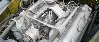
The Gorky Automobile Plant team began designing vehicles in 1956. The project was led by V.A. Dedkov. In 1958, engineers prepared the first prototype. The sample was equipped with a GAZ-40P carburetor power unit, which developed up to 90 hp.
The first tests showed that the power is not enough to provide the required cross-country ability. Engineers tried to introduce a YaAZ-206B diesel engine (205 hp) into the design, but due to its large mass, this idea was abandoned. To compensate for the lack of power, they decided to place two 40P engines in the engine compartment. For stable operation of all bridges, the designers assembled a unique transmission. The final version was prepared in the second half of 1959.
The BTR-60 was ahead of many competitors, which were created on a competitive basis in the 50s. Simplicity, reliability and low cost - this is why Gorky’s project became the winner of the state competition.
The selection committee of the Ministry of Automotive Industry was skeptical about the idea of pairing two engines. The military liked this option: in the event of a failure of one power unit, the vehicle could travel to the technical center on one (the maximum speed on the highway is 60 km/h). On November 13, 1959, the Ministry of Defense accepted the equipment into service.
Design and equipment of the Soviet combat vehicle
The hull protection of the BTR-60 is quite weak. It can protect against fragments of grenades and bullets fired from a machine gun, but a heavy machine gun can easily penetrate it. The steel sheets are only 5-9 mm thick. During the war in Afghanistan, soldiers quickly realized that hiding inside the hull of the BTR-60 was not worth it. If the car was blown up by a mine, then there was little chance of survival.
The hull itself was made in a streamlined shape, which made it easier for the armored personnel carrier to move in water. The BTR-60PB modification received a completely enclosed body with radiation protection. To protect against the penetration of dirty air, a special filter unit was used. The captain and mechanic are located in the front, the paratroopers are in the middle, and the engines and transmission are located in the rear.
The BRR-60PB received a cone-shaped turret. It had the same weak armor as the hull. The shooter was placed in a turret, which rotated using a special screw mechanism.
As for the armament of the armored personnel carrier, the basic modification had only three SGBM machine guns. After several minor modifications, it was decided to replace these machine guns with more advanced PCBs. The BTR-60PB modification received a more serious weapon - a 14.5 mm KPVT heavy machine gun. With such weapons, the BTR-60 could easily deal with lightly armored enemy vehicles. In addition to machine guns, grenades were used as additional weapons, of which there was an impressive supply.
Screw mechanisms were used for aiming at the target, and a periscope-type optical sight was used for aiming. If a large-caliber machine gun was used for lightly armored vehicles, then the PKB was usually fired at living targets located within a radius of up to 1,500 meters.
To monitor the terrain in the BTR-60, the following devices were used:
- B-1 in the amount of 6 pieces was installed on copies of the first issues;
- After some time, the captain of the armored personnel carrier received the TPKU-2B device;
- TVN-1 and TVN-2 were devices for monitoring terrain in conditions of limited visibility.
In addition, to view the area in a calm situation, two inspection hatches located in the frontal part of the vehicle were used.
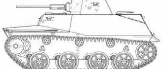
Chassis and water cannon BTR-60
When creating an armored personnel carrier, an 8x8 wheel arrangement was used. Since the controllability of the prototype with traditional steering was insufficient, it was decided to make the two front axles steerable. The design of single-ply tires allows them to withstand a bullet hit. Two compressors are capable of inflating tires remotely. This helps not only to move with a broken tire, but also to change the pressure depending on the type of terrain.
The wheels are located on two levers connected to the body by hinges. Each upper arm, except the third axis, has two hydraulic shock absorbers. The BTR-60's suspension is independent, torsion bar. An armored personnel carrier can continue to move even if two wheels are completely lost.
The water jet device of the armored personnel carrier is powered by GAZ-40P engines. It is located under the motor and has a propeller. To prevent the propeller from being damaged, it was covered with a grille on one side and an armored flap on the other.
The BTR-60 and its modifications have proven themselves in most combat conflicts of the 20th century. Because the Soviet Union helped developing countries, these armored personnel carriers can now be found in the armies of developing countries around the world.
general information
The 60th model became the first four-axle armored personnel carrier. The development of the line of this equipment continues in our years. For 16 years (1960-1976) it was produced at the Gorky Automobile Plant. Until 1987, the Kurgan plant of wheeled tractors was producing. Another production point was located in Romania. Local specialists assembled equipment under Soviet license (TAV-71).
Until the end of the 60s, the BTR-60 was the main all-terrain vehicle in the Soviet army. In the 70-80s, the number in the army decreased significantly due to the release of the 70 and 80 models. The vehicle went through many combat operations, including the Afghan War. Exports were carried out to dozens of countries around the world. Despite its impressive age, the equipment operates in the army units of 47 countries (data for 2007).
Nowadays, the BTR-60 blocking technology is popular. The most common application is the introduction into the design of UAZ vehicle bridges. In many online stores you can buy a BTR-60 lock, both new and old. It’s difficult to talk about the difference in quality; everyone finds certain advantages for themselves. The average cost for civilian transport is 8-12 thousand rubles, for military transport - up to 19,500.
Modification of BTR-60PB
In 1966, a major modernization of the combat vehicle was carried out. The improved model received the BTR-60PB index and the following design changes:
- A turret from BDRM-2 with a 14.5 mm KPVT heavy machine gun and a 7.62 mm PKT machine gun was installed. This significantly increased the combat power of the armored personnel carrier, moving it into a more effective class of military equipment;
- The number of troops transported was reduced to 8 people, one of whom was supposed to serve as a shooter in the turret;
- Additional surveillance devices appeared;
- The troop compartment now has hatches suitable for quick landing or disembarkation;
- Frontal protection has been slightly strengthened;
- Anti-nuclear protection has been strengthened.
The new modification of the BTR-60PB turned out to be the most successful version of the BTR-60 armored personnel carrier. They were produced unchanged until 1976. The BTR-60 differential lock showed good performance during operation, so it was left unchanged. There is evidence that the BTR-60PB was produced at plants other than GAZ until 1987. Western sources claim that in total about 25,000 BTR-60 and BTR-60PB were produced in the USSR. These armored personnel carriers are still used in many armies around the world.