Spare parts for GAZ, ZIL, HYUNDAI trucks
If you need original spare parts at minimal prices for GAZ, ZIL or HYUNDAI trucks, we invite you to visit the wholesale and retail store-warehouse.
Our company was founded back in 1998. Over the years, we have accumulated extensive experience in various areas of cargo and passenger vehicles, and today we offer our clients the most favorable terms of cooperation.
Our team of specialists, always in the shortest possible time and professionally, will help you choose a quality part for any buyer at the best price.
The company supplies automobile spare parts to many public and private motor transport enterprises in St. Petersburg, the Leningrad region and the North-Western region. We constantly serve individual entrepreneurs and individuals.
VOSTOK works with all regions of Russia, as well as with Kazakhstan and Belarus. Delivery of orders is carried out through transport companies. The choice of courier service is agreed with the client individually.
We are official representatives of enterprises that produce spare parts for GAZ, ZIL and HYUNDAI .
Our warehouse always has more than 6,000 different types of spare parts for domestic and Korean trucks and buses, many of which are not available in other stores.
Today we have exclusive parts for the Chinese YUTONG ZK6737D buses on sale at a big discount.
Only our company offers customers the widest range of TAYA leaf clutches, suitable for most cars and trucks and MTZ-80.82 tractors. With us you can always buy auto parts at the time of contact, without pre-ordering and waiting for receipt, both in cash and by bank transfer.
A flexible system of discounts is provided for regular customers.
You can view the spare parts catalog in the “Catalogue” or “Price List” sections.
GAZ 33104 and 33106 GAZ-3310 (Valdai)
Serially produced since 2004.
The car is equipped with a 4-cylinder, 4-stroke diesel engine with liquid cooling and turbocharging, model MMZ D-245.7 E-2, E-3. GAZ-3310 is a two-axle vehicle, with an on-board platform and a folding tailgate, arches and an awning. There are trim levels with an extended wheelbase and a six-seat cabin with two rows of seats. From us you can purchase all the parts for this machine directly from the warehouse. Prices for spare parts are presented in the spare parts catalog for GAZ-33104 and 33106 GAZ 3310 Valdai.
Specifications
ZIL-433362 has the following technical characteristics:
- Wheel formula - 4x2.
- Dimensions: length 6.6 m, width 2.4 m, height 2.6 m.
- Maximum cargo weight is 6830 kg.
- Vehicle weight - 3945 kg.
- The permissible chassis weight is 11200 kg.
- The maximum weight of the road train is 19200 kg.
- Permissible load on the road surface from the curb weight through the tires: front wheels - 21750 N, rear axle - 17700 N.
- The greatest load on the road surface from the total weight of the vehicle through the tire of the front wheels is 30,000 N, the rear axle is 82,000 N.
- The turning radius is 6.9 m.
- The highest speed with the full weight of the truck is 90 km/h, with the full weight of the road train - 80 km/h.
- Fuel tank volume - 170 l.
Engine
The car is equipped with a ZIL-508 carburetor engine. This is an 8-cylinder engine with a capacity of 6 liters. Motor power 150 hp, or 110 kW. Engine speed is 3200 per minute. The torque is 41 kgf/m. The motor design is equipped with valves located at the top. A total of 16 valves are installed. Engine weight with additional equipment is 640 kg.
GAZ 3302 Gazelle
Serially produced since 1994. Equipped with a 4-cylinder in-line 4-stroke gasoline engine model ZMZ 40522.10, rated at 152 hp. The range of various modifications of "Gazelle" is extensive: one and a half ton trucks with a standard or extended wheelbase, vans and 7-seater combi cars, cars with isothermal and manufactured goods vans with a cargo space volume of 13 to 18 m3, minibuses with a different number of passenger seats. Has a load capacity of up to 1500 kg. Gazelle cars, depending on the modification, have both rear-wheel drive and all-wheel drive, which is very important for operation in off-road conditions and harsh Russian winters. You can always purchase spare parts for this model from us to order. We have the shortest delivery times and low prices. Vehicles of this brand are real competitors to domestic trucks in Russia. Despite the higher cost of spare parts, compared to Gazelle or Bychk, Hyundai trucks have such advantages as reliability, significantly longer service life, European quality, comfort, developed car service, adaptation to Russian fuel, as well as high environmental standards. More details about these trucks can be found here.
Device
The cabin has 3 seats, 2 doors, panoramic glass, which provides excellent visibility. Large rear view mirrors are located on brackets. Door windows can be manually lowered and secured. The doors open at right angles, which is convenient for the driver and passengers. The cabin is equipped with large steps.
The height of the cabin is 2700 mm, it can be equipped with a berth. The steering has a mechanical and hydraulic drive. The hydraulic distributor and cylinder help improve steering control. Modern heating and ventilation systems have been installed.
The car is equipped with a 5-speed gearbox. The cardan system includes a chassis on which 2 shafts and intermediate supports are installed, which are connected by crosspieces. The load is transferred to the axles using the drive axle.
The supporting structure consists of a frame made of 2 metal channel beams. Longitudinal sections are fixed with cross members. Smooth movement is ensured by the design of the axle suspension. In the front and rear parts of the structure there are springs with shock absorption.
The rear springs are supplemented with metal sheets for strength. The truck is compatible with a large number of additional add-ons. The most commonly used emergency repair equipment includes a diesel generator mechanism with a repair shop and a fuel supply. The universal chassis allows tool boxes to be placed underneath. The machines are used to perform repair work at remote sites.
Ambulance vehicles, fuel tankers and garbage trucks, hydraulic lifts, tankers, loaders, dump trucks, bunker vehicles and other equipment are represented by this truck. The car can be used on any type of road.
The machine is characterized by increased maneuverability, maneuverability, operational reliability and ease of maintenance.
- power supply with standard connectors;
- versatility of the coupling device;
- connecting trailer brakes to vehicle systems.
The machine can transport bread, food, industrial products, frozen foods (refrigerated trucks). Hydraulic lifts can be used in the construction and installation of structures.
Brake system
The vehicle's braking system consists of 3 circuits and includes: a service brake with pneumatic control and a 2-circuit hydraulic system along the axles on the front and rear wheels. The axles have drum shoes with the possibility of installing anti-locking. There is a parking and spare brake with a drive circuit, pneumatic transmission, and drum shoes. If the cargo chassis is used as part of a road train, then the circuit is equipped with a crane to control the trailer brake.
Electrical equipment
The vehicle's electrical system is single-wire, with a voltage of 12 V. The ignition has a contact-transistor design. Starter voltage is 12 V, remote control and electromagnetic load relay are installed.
There is a 12 V battery, brand 6-ST-81, with a capacity of 81 A/h. The G-130 series alternating current generator creates a direct current of 28 A and a power of 350 W. The same voltage is maintained at different speeds using an electromechanical relay and an electronic control circuit.
The electrical equipment can be equipped with additional options: a pre-heater to make starting the engine easier in cold weather. A bed heating system can be installed. An upgraded ignition circuit with microprocessors is installed. The electrical circuit makes it possible to install an insulation cover and a recoil bar.
Spare parts for Ural, Kraz, MAZ, Kamaz trucks. Engine parts YaMZ-236, YaMZ-238
__________________________________________________________________________
__________________________________________________________________________
Brakes and steering of ZIL-4331 cars
___________________________________________________________________________
Pneumatic drive of brakes of a ZIL-4331 car. The pneumatic drives of brake systems with multi-circuit drives of cars ZIL-4331, 433360, 431410, etc.) have a lot in common in the purposes and design of autonomous circuits, in the pneumatic drive and the devices used.
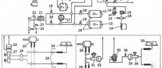
Rice. 2. Diagram of the pneumatic drive of the brake systems of the ZIL-4331 car 1 - compressor; 2 — brake chambers of the front wheels; 3—control valves; 4 — pressure limitation valve; 5 — pneumoelectric sensors for turning on the brake signal; 6 — auxiliary brake system valve; 7 — air distributor; 8 — emergency parking system release valve; 9, 11 — air cylinders of the service brake system; 10 — condensation air cylinder; 12 — taps for draining condensate; 13 — pneumoelectric sensors for pressure drop in brake systems; 14 - triple safety valve; 15 — parking brake valve; 16 — pneumatic cylinders for driving the auxiliary brake system mechanisms; 17 — two-pointer pressure gauge of the service brake system; 18 — two-section valve of the service brake system; 19 — double safety valve; 20 — pressure regulator; 21 — fuse against condensate freezing; 22 — air cylinder of the parking brake system with a sensor for its activation; 23 — air cylinder of the auxiliary brake system; 24 — control valve for the brake system of a trailer (semi-trailer) with a single-wire drive; 25 — control valve for the brake system of a trailer (semi-trailer) with a two-wire drive; 26—single safety valve; 27— accelerator valve; 28 — brake chambers of the rear wheels; 29 — quick release valve; 30 — brake force regulator; 31 — two-line bypass valves; 32, 33 - connecting heads The diagram of the pneumatic drive of the brakes of the ZIL-4331 car is shown in Fig. 2. Compressed air from compressor 1 through the pressure regulator 20, the condensate freeze guard 21, the condensation air cylinder 10 is supplied to the block of protective valves (double 19 and triple 14), which distribute the air, filling the air cylinders of the first four independent circuits: - brake drive front wheels (contour /); — rear wheel brake drive (circuit //); drive of the parking and spare brake systems, as well as the combined drive of the brakes of a trailer or semi-trailer (circuit ///); — auxiliary brake drive and power supply to other pneumatic devices, including vehicle transmission units (circuit IV). Along with this, there is a V drive circuit for the emergency brake release system, which does not have its own air cylinder.
All air cylinders have valves 12 for draining condensate, and all circuits have built-in pneumatic-electric sensors 13 for compressed air pressure drop. A two-pointer pressure gauge 17 is connected to the air cylinders of the two first circuits of the drive mechanisms of the ZIL-4331 service brake system. To check the operation of the brake systems, valves 3 control outlets are installed at various points of the pneumatic drive, to which portable pressure gauges are connected. Circuit I includes an air cylinder 11, a pressure drop sensor 13, a lower section of the brake valve 18, a pressure limiting valve 4, brake chambers 2 of the front wheels and a control valve 3. Circuit II includes an air cylinder 9, a pressure drop sensor 13, an upper section of a valve 18, a brake force regulator 30 with an elastic element, a control valve 3 and brake chambers 28 of the ZIL-4331 rear wheels. Circuit III includes an air cylinder 22, a pressure drop sensor 13, a manually operated parking brake valve 15, an accelerator valve 27, two dual-line bypass valves 31, a quick brake release valve 29, a control valve 3, spring energy accumulators located in the brake chambers 28 rear wheels. This circuit also includes: a single safety valve 26, trailer (semi-trailer) brake control valves 25 and 24, respectively, with a two-wire and a single-wire drive, two automatic connection heads 32, one connection head 33 (type A) and a brake signal sensor 5 that provides light signal when any ZIL-4331 brake system is operating. Circuit IV includes an air cylinder 23, a pressure drop sensor 13, a push-button valve 6 for turning on the auxiliary brake, two pneumatic cylinders 16, a brake signal sensor 5, a control valve 3 and an air distribution box 7, which is designed to supply compressed air to the clutch pneumatic booster, switch gears in the divider, pneumatic windshield wipers and other consumers of compressed air. Circuit V includes a push-button pneumatic valve 8 for emergency release of the parking brake, a dual-line bypass valve 31, a triple safety valve 14 and brake chamber energy accumulators 28. Steering control of ZIL-4331 vehicles The main condition for trouble-free and durable operation of the ZIL-4331 steering control is keeping it clean hydraulic system.
For power steering, only clean filtered oil is used, which is poured through a funnel with a double mesh and a filler filter installed in the pump reservoir. The use of contaminated oil causes rapid wear of the pump and hydraulic booster. The power steering system is filled at the manufacturer with all-season oil for hydraulic systems of R-brand vehicles (TU 38-1011792-71). This oil has a low pour point and contains anti-wear, antioxidant and other additives that improve its quality. When operating the ZIL-4331 power steering system filled with oil P, it is only added to the pump reservoir if necessary. An oil change is performed only when repairing power steering system units. In the absence of oil P, it is permissible to add oils recommended by the manufacturer as substitutes. However, the durability of the pump and steering mechanism is reduced. When adding substitute oil, the oil is changed 2 times a year (in autumn and spring). Rules for adding and changing oil, as well as brands of substitute oils, are given in the “Steering Maintenance” section. If the hydraulic booster fails due to damage to the ZIL-4331 power steering pump or the hydraulic booster itself, or destruction of the pump drive hose or belt, you can only use the steering mechanism for a short time, until the malfunction is eliminated. Long-term operation of a vehicle with inoperative power steering leads to rapid wear of the steering mechanism or its breakdown, since this overloads the thrust ball bearings, steering screw and other parts of the ball nut assembly. The wear of the driveshaft and steering column also accelerates. For the same reason, it is not allowed to tow a car for a long time with the engine not running without hanging its front axle. It is prohibited to stop the engine until the vehicle comes to a complete stop, and also to move with the engine not running on descents or coasting along a horizontal section of the road. In these cases, the ZIL-4331 power steering pump stops working and the force on the steering wheel and on the steering mechanism parts increases sharply. When maneuvering and getting out of deep ruts when driving on bad country roads, it is forbidden to hold the steering wheel turned all the way in one direction or another for a long time.
In this case, the pump operates on the safety valve, which causes rapid heating of the oil and can lead to pump failure. To continue driving in the event of failure of the power steering hoses of the ZIL-4331, connect the discharge hole of the pump to the return pipe on the pump reservoir, close the discharge and return holes of the steering mechanism with wooden plugs or in another way that provides protection against the ingress of dirt or foreign bodies, and add oil. With such movement, the engine must operate at the lowest possible crankshaft speed; monitor the temperature of the oil in the pump reservoir and if it gets too hot, stop the car so that the oil cools down.
_________________________________________________________________________
_________________________________________________________________________
_________________________________________________________________________
- Cardan shafts and power take-off Ural-4320
- Transmission gearbox Ural-4320
- Bridges Ural-4320
- Transfer case Ural-4320
- Steering Ural-4320
- Truck cranes and cranes based on trucks
_________________________________________________________________________
_________________________________________________________________________
- Cylinder block and cylinder head YaMZ-236 HE2, YaMZ-236 BE2
- Checking and adjusting YaMZ-236
- Power system and lubrication system YaMZ-236
- Driven and driven clutch discs YaMZ-236, 238
- Cooling and lubrication systems YaMZ-238
- Fuel injection pump YaMZ-238
_________________________________________________________________________
- Kamaz diesel engine
- Repair and adjustment of Kamaz power steering
- Kamaz-152 gearbox with divider
- Gearbox parts for Kamaz-5320 gearbox
- Kamaz transfer case and driveshafts
- Kamaz gearbox repair
- Clutch KamAZ-5320
- Construction of Kamaz-4310 drive axles
- Power steering MAZ-5551, 5549, 5335, 5336, 5337
- Front axle and steering rods MAZ-5551, 5549, 5335, 5336, 5337
- Clutch adjustment MAZ-5551, 5549, 5335, 5336, 5337
- Adjustment and repair of gearboxes MAZ-5551, 5549, 5335, 5336, 5337
- Repair and maintenance of the rear axle MAZ-5551, 5549, 5335, 5336, 5337
- Front axle parts and steering rods MAZ-5516, 5440
- Steering Maz-5516, 5440
- Details of driving axles Maz-5516, 5440
- Clutch device ZIL-130
- Repair of ZIL-130 gearbox
- Repair of rear axle ZIL-130
- Basic parts of the ZIL-130 engine
- Transfer case and power take-off ZIL-131
- Drive axles ZIL-131
- Steering ZIL-131
- Maintenance of ZIL-645 engine parts
Disassembly and assembly of a combined brake valve.
To disassemble the tap, unscrew the cover together with cover 2 (see Fig. 12-22) and disconnect the tap drive rod 1 from lever 3, then remove the cover. To remove the lever housing, unscrew the bolts securing the lever housing to the valve body 8. If necessary, remove the roller with cam 25 and the axle with small lever 29 from the lever body by pressing it out of the lever body.
To remove the large lever 3 from the rod 7, it is necessary to press out its axis and remove it together with the rod 1.
brake valve
Fig. 12-22. Combined brake valve with single-circuit brake actuator:
1 — brake valve drive rod; 2 — protective cover; 3 - large lever; 4 — stop of the large lever; 5 — spring of the equalizing section that controls the trailer brakes; 6 — rod guide bushing; 7 — rod; 8 — body; 9 - membrane; 10 and 17 — exhaust valve seats; 11 O-ring; 12 and 18 — exhaust valves; 13 — adjusting shims; 14 and 19 — intake valves; 15 — intake valve seat; 16 - cover; 18 - cover; 20 – membrane of the brake signal switch; 21 — contact connecting plate; 22 — contact spring; 23 - clamps of the brake signal switch; 24 - moving contact; 25 — switch body; 26 — channel for supplying compressed air to the brake signal switch membrane; 27 — balancing spring of the section that controls the trailer brakes; 28 — balancing spring cup; 29 — small lever; 30 - lock nut; 31 — rod stroke limiter; 32 — shaft of the manual drive lever; 33 — lever connected to the parking brake drive; 34 — stop of the manual drive lever. The arrows indicate the direction of air movement: A - in the line of the trailer; B - to the brake chambers of the tractor; C - from an air cylinder; D - into the environment.