The article for translation was proposed by alessandro893. The material is taken from an extensive reference site, describing, in particular, the principles of operation and design of radars.
An antenna is an electrical device that converts electricity into radio waves and vice versa. The antenna is used not only in radars, but also in jammers, radiation warning systems and communications systems. During transmission, the antenna concentrates the energy of the radar transmitter and forms a beam directed in the desired direction. When receiving, the antenna collects the returning radar energy contained in the reflected signals and transmits them to the receiver. Antennas often vary in beam shape and efficiency.
On the left is an isotropic antenna, on the right is a directional antenna
Dipole antenna
A dipole antenna, or dipole, is the simplest and most popular class of antennas. Consists of two identical conductors, wires or rods, usually with bilateral symmetry. For transmitting devices, current is supplied to it, and for receiving devices, a signal is received between the two halves of the antenna. Both sides of the feeder at the transmitter or receiver are connected to one of the conductors. Dipoles are resonating antennas, that is, their elements serve as resonators in which standing waves pass from one end to the other. So the length of the dipole elements is determined by the length of the radio wave.
Directional pattern
Dipoles are omnidirectional antennas. For this reason, they are often used in communication systems.
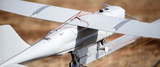
Radar on board
The idea of using radar equipment on airplanes came several years after the first ground-based radars appeared. Although radio engineering equipment began to be used in radio navigation systems and “blind landing” devices already in 1933.
In the USSR, it was the Redut ground station that was the prototype of the first airborne radar station (BRLS). One of the main problems was the placement of the equipment on the aircraft - the station set with power supplies and cables had to weigh approximately 500 kg. It was impossible to install such equipment on a single-seat fighter of that time. And a solution was found - it was decided to place the station not on a single-seat aircraft, but on a two-seat Pe-2.
Radar "Korshun" on the MiG-17P
The first domestic airborne radar station was named "Gneiss-2", and in June 1943 it was put into service. By the end of 1944, more than 230 Gneiss-2 stations were produced.
And in the victorious year of 1945, serial production of the Gneiss-5s aircraft radar station began. The target detection range reached 7 km. But the main novelty of this modification was that, starting from a range of 1.5 km, air traffic data was duplicated on a special indicator installed in the cockpit. This allowed the pilot to independently launch the aircraft into an attack.
The further development of airborne radars was associated with the advent of jet aircraft. Installations such as “Emerald”, “Falcon” and “Sapphire” in various modifications helped to detect enemy aircraft and cruise missiles.
Antenna in the form of an asymmetric vibrator (monopole)
An asymmetrical antenna is half of a dipole antenna, and is mounted perpendicular to the conducting surface, a horizontal reflecting element. The directivity of a monopole antenna is twice that of a double-length dipole antenna because there is no radiation underneath the horizontal reflective element. In this regard, the efficiency of such an antenna is twice as high, and it is capable of transmitting waves further using the same transmission power.
Directional pattern
Wave channel antenna, Yagi-Uda antenna, Yagi antenna
Yagi antenna is a directional antenna consisting of several parallel elements located on the same line. They often consist of a single feed element, usually a dipole or loop vibrator. Only this element experiences excitement. The remaining elements are parasitic - they reflect or help transmit energy in the desired direction. The irradiator (active vibrator) is usually located second from the end, as in the picture below. Its size is selected in order to achieve resonance in the presence of parasitic elements (for a dipole this is usually 0.45 - 0.48 of the wavelength). The element to the left of the irradiator is a reflector (reflector). It is usually longer than the irradiator. There is usually only one reflector, since adding additional reflectors has little effect on efficiency. It affects the power ratio of the antenna signals radiated in the back/forward directions (gain in the maximum direction relative to the opposite direction). To the right of the feed are director elements, which are usually shorter than the feed. The Yagi antenna has a very narrow operating frequency range, and the maximum gain is approximately 17 dB.
Directional pattern
AFAR and “smart skin” for the Su-57
Modern radars provide detection and tracking of air and ground targets in air-to-air and air-to-surface modes, as well as radio correction, flight missions and target designation for the use of guided airborne weapons.
One of the modern Russian developments in the field of radar is the first domestic airborne radar with an active phased antenna array (AFAR) “Zhuk-AE” for the MiG-35 fighter. In it, the developers applied the latest technologies in the field of radio electronics, thanks to which the Zhuk has no equal in terms of efficiency to cost ratio not only in Russia, but also on the international market.
Radar "Zhuk-AE"
The antennas of the N036 Belka radar station for the newest Russian Su-57 fighter are also made using AFAR technology. Note that the presence of an AFAR is one of the conventional features of fifth-generation fighters.
In 2022, Russian fifth-generation Su-57 fighters received the so-called “smart skin.” The antennas of the N036 Belka station are located not only in the nose of the vehicle, but are also distributed over the surface of the aircraft, six in total, but the exact configuration has not yet been disclosed. Most of the characteristics of the Su-57 radar system are still unknown. But the developers said that during flight tests the N036 Belka station confirmed the declared parameters.
According to experts, such a “smart skin” will provide pilots of the Russian fifth-generation fighter with new capabilities, in particular, all-round visibility for hundreds of kilometers. The use of antennas operating in different bands is also recognized as an effective response to American stealth technologies.
Corner antenna
A type of antenna often used on VHF and UHF transmitters. It consists of an irradiator (this can be a dipole or a Yagi array) mounted in front of two flat rectangular reflective screens connected at an angle, usually 90°. A sheet of metal or a grating (for low-frequency radars) can act as a reflector, reducing weight and reducing wind resistance. Corner antennas have a wide range, and the gain is about 10-15 dB.
Directional pattern
Helix antenna
A helical antenna consists of a conductor twisted into a spiral. They are usually mounted above a horizontal reflective element. The feeder is connected to the bottom of the spiral and the horizontal plane. They can operate in two modes - normal and axial.
Normal (transverse) mode: The helix dimensions (diameter and inclination) are small compared to the wavelength of the transmitted frequency. The antenna operates in the same way as a shorted dipole or monopole, with the same radiation pattern. The radiation is linearly polarized parallel to the axis of the spiral. This mode is used in compact antennas for portable and mobile radios.
Axial mode: the dimensions of the spiral are comparable to the wavelength. The antenna works as a directional one, transmitting the beam from the end of the spiral along its axis. Emits radio waves of circular polarization. Often used for satellite communications.
Directional pattern
Rhombic antenna
A diamond antenna is a broadband directional antenna consisting of one to three parallel wires fixed above the ground in the shape of a diamond, supported at each vertex by towers or poles to which the wires are attached using insulators. All four sides of the antenna are the same length, usually at least the same wavelength, or longer. Often used for communication and operation in the decameter wave range.
Directional pattern
Two-dimensional antenna array
Multi-element array of dipoles used in the HF bands (1.6 - 30 MHz), consisting of rows and columns of dipoles. The number of rows can be 1, 2, 3, 4 or 6. The number of columns can be 2 or 4. The dipoles are horizontally polarized and a reflective screen is placed behind the dipole array to provide an amplified beam. The number of dipole columns determines the width of the azimuthal beam. For 2 columns the beam width is about 50°, for 4 columns it is 30°. The main beam can be tilted 15° or 30° for maximum coverage of 90°.
The number of rows and the height of the lowest element above the ground determines the elevation angle and the size of the serviced area. An array of two rows has an angle of 20°, and an array of four has an angle of 10°. The radiation from a two-dimensional array usually approaches the ionosphere at a slight angle, and due to its low frequency, is often reflected back to the earth's surface. Since radiation can be reflected many times between the ionosphere and the ground, the antenna's action is not limited to the horizon. As a result, such an antenna is often used for long-distance communications.
Directional pattern
Horn antenna
A horn antenna consists of an expanding horn-shaped metal waveguide that collects radio waves into a beam. Horn antennas have a very wide range of operating frequencies; they can operate with a 20-fold gap in its boundaries - for example, from 1 to 20 GHz. The gain varies from 10 to 25 dB, and they are often used as feeds for larger antennas.
Directional pattern
Parabolic antenna
One of the most popular radar antennas is the parabolic reflector. The feed is located at the focus of the parabola, and the radar energy is directed to the surface of the reflector. Most often, a horn antenna is used as a feed, but both a dipole and a helical antenna can be used.
Since the point source of energy is at the focus, it is converted into a wavefront of constant phase, making the parabola well suited for use in radar. By changing the size and shape of the reflective surface, beams and radiation patterns of various shapes can be created. The directivity of parabolic antennas is much better than that of a Yagi or dipole; the gain can reach 30-35 dB. Their main drawback is their inability to handle low frequencies due to their size. Another thing is that the irradiator can block part of the signal.
Directional pattern
Death rays and British radars
Now let's go to Great Britain, which by 1935, unlike Germany, the USA and the USSR, did not have great success in the development of radars. It is interesting that the British defense industry was prompted to create the first radar by rumors that the Germans had death ray generators capable of destroying enemy aircraft at a distance. National Physical Laboratory radiophysicist Robert Watson-Watt, a descendant of the inventor of the steam engine, James Watt, was assigned to check the possibility of creating such a weapon.
Together with his assistant, the scientist proved the utopia of destroying aircraft with rays, but in the process of work he came to the conclusion that radio waves reflected from the aircraft can be captured and thereby detect enemy equipment. The physicist approached the customer with the idea of developing a radio detector.
Robert Watson-Watt conducts first radar tests
Watson-Watt's initiative was supported, and on February 26, 1935, he conducted the first successful tests of his radio direction finder, which managed to detect a flying bomber at a distance of 13 km. By 1936 this figure had reached 150 km. By the outbreak of World War II, Britain had built the world's first national radar defense system. It included more than 20 stations and blocked approaches to the British Isles in all main directions of a possible attack. The stations were located along the coast in a chain, which is why the system was called Chain Home.
Robert Watson-Watt's invention stopped the German air invasion of the British Isles. The radars detected enemy aircraft and gave British air defense forces a 20-minute advantage. Over the course of three months, the Germans lost 1,887 vehicles over the British coast - almost half of the entire battle fleet.
Cassegrain antenna
A Cassegrain antenna is very similar to a conventional parabolic antenna, but uses a system of two reflectors to create and focus the radar beam. The main reflector is parabolic, and the auxiliary reflector is hyperbolic. The irradiator is located at one of the two foci of the hyperbola. The radar energy from the transmitter is reflected from the auxiliary reflector onto the main one and focused. The energy returning from the target is collected by the main reflector and reflected in the form of a beam converging at one point onto the auxiliary one. It is then reflected by an auxiliary reflector and collected at the point where the irradiator is located. The larger the auxiliary reflector, the closer it can be to the main one. This design reduces the axial dimensions of the radar, but increases the shading of the aperture. A small auxiliary reflector, on the contrary, reduces shading of the opening, but it must be located away from the main one. Advantages compared to a parabolic antenna: compactness (despite the presence of a second reflector, the total distance between the two reflectors is less than the distance from the feed to the reflector of a parabolic antenna), reduced losses (the receiver can be placed close to the horn emitter), reduced side lobe interference for ground radars. Main disadvantages: the beam is blocked more strongly (the size of the auxiliary reflector and feed is larger than the size of the feed of a conventional parabolic antenna), does not work well with a wide range of waves.
Directional pattern
Radar station
(radar), radar, radar, device for monitoring various objects (targets) using
radar methods.
The main components of a radar are transmitting and receiving devices located at one point (the so-called combined radar) or at points remote from each other at some (usually significant) distance (two- and multi-position radars);
in radars used for passive radar,
there is no transmitter. The antenna can be common for the transmitter and receiver (for a combined radar) or separate antennas can be used (for multi-position radars). An important component of the radar receiving device (after the receiver itself) is a light indicator on a cathode ray tube (CRT), and in modern (mid-70s) radars, along with the indicator, there is a digital computer that automates many operations for processing received signals. The main characteristics of the radar: measurement accuracy, resolution, limit values of a number of parameters (maximum and minimum range, sector and viewing time, etc.), noise immunity. The main characteristics also include the mobility of the radar, its weight, dimensions, power supply, service life, number of maintenance personnel and many other operational parameters.
The emergence and development of radar.
The first radars were aircraft detection stations. 5 stationary pulse radars were installed on the southwest coast of Great Britain in 1936. They operated on relatively long (meter) waves, were very bulky and could not detect aircraft flying at low altitude. Nevertheless, a chain of such stations was soon established along the entire English coast of the English Channel; it showed its effectiveness in repelling German air raids during World War II (1939–45). In the USA, an experimental pulse radar was installed on a ship and underwent comprehensive testing in 1937. After this, work on creating radars for various purposes received rapid development in the USA, and by the beginning of the 40s. Centimeter-wave radars were created to detect aircraft flying at great distances.
In the USSR, the first experiments in radio detection of aircraft were carried out in 1934. Industrial production of the first radars put into service began in 1939. These stations (RUS-1) with continuous radiation modulated by sound frequency, were located in a chain along a certain line and made it possible to detect an aircraft , crossing this line. They were used on the Karelian Isthmus during the Soviet-Finnish War of 1939–40 and in the Caucasus during the Great Patriotic War of 1941–45. The first pulse radar installation was tested in 1937. Industrial production of pulse radars (RUS-2, Redut) began in 1940. These stations had one transmitting and receiving antenna and were placed together with a power source in the back of a car. They made it possible to detect aircraft with a 360-degree view of the airspace at distances (depending on flight altitude) of up to 150 km.
In 1940, the Leningrad Institute of Physics and Technology (head of work Yu. B.
Kobzarev
) completed the construction of a stationary radar for the air defense system.
The station's antennas were located at a high altitude (20 m
), which provided a large detection range (~ 250
km
) and made it possible to detect relatively low-flying aircraft.
During the Great Patriotic War, in addition to the Redut stations, the production of reliable portable Pegmatit stations was launched, which could be easily transported in packaged form and quickly installed in any room. Subsequently, the Pegmatit stations were improved so that they made it possible to determine, in addition to the range and azimuth of the aircraft, its altitude. At the end of the war, the improvement of radars took place in the direction of both increasing their range and measurement accuracy, and automating individual operations through automatic tracking systems
for measuring range and tracking by angular coordinates (in gun aiming stations), automatic counting devices (in stations for “blind” » bombing), etc.
After World War II, with the development of aviation (increasing altitude, flight speed and maneuverability of aircraft), the need arose to create radars capable of operating in difficult conditions - with a large number of objects and the influence of deliberate interference. Increasing the accuracy of coordinate measurement (including thanks to new methods for measuring them), pairing the radar with computers and the general radio control system for missiles have significantly changed the technical and tactical parameters of the radar, which have become the most important link in the automated control system for air defense systems.
Appearance in the 50-60s. rocket and space technology led to the creation of radars to solve a number of new problems (see article Radar
).
A variety of radars have been developed to solve many problems in science and the national economy (see, for example, Radio Navigation System, Meteor Radar, Planetary Radar, Radar Astronomy, Radar in Meteorology
, etc.).
Main types of radar.
Radars are distinguished primarily by specific tasks that they perform autonomously or in a complex of means with which they interact, for example: radar for air traffic control systems, radar for detecting or targeting anti-aircraft guided missiles of air defense systems, radar for searching for spacecraft (SC) and rendezvous with them, aircraft all-round or side-view radars, etc. The specificity of solving individual problems and their wide range have led to a wide variety of radar types. For example, to increase the accuracy of shooting at aircraft, miniature radars are installed in the heads of anti-aircraft projectiles, measuring the distance from the projectile to the object and activating (at a certain distance) the fuse of the projectile; To promptly warn an aircraft that another aircraft is approaching from its “tail”, a “tail protection” radar is installed on it, which automatically generates a warning signal.
Depending on the location of the radar installation, there are ground, sea, aircraft, satellite radars, etc. Radars are also divided according to technical characteristics: by carrier frequency
(operating wavelength range) - on radars of meter, decimeter (DM), centimeter (CM), millimeter (MM) and other ranges; by methods and operating modes - on radars pulsed and with continuous radiation, coherent and with incoherent operating modes, etc.; according to the parameters of the most important radar components - transmitter, receiver, antenna and received signal processing system, as well as other technical and tactical parameters of the radar.
Precise coordinate measurement radars, called gun guidance stations (SON), determine with a high degree of accuracy the coordinates (azimuth, elevation, range) of air, sea and ground objects ( Fig. 1
). For anti-aircraft artillery, the appearance of these stations meant a technical revolution. A sharp increase in the accuracy of measuring coordinates, primarily angular ones, became possible after mastering the SM wave range, which made it possible to generate highly directional radiation of radio waves in SONs using antennas. At the same time, the use of radiated power in the required directions sharply increased and it was possible to significantly get rid of the influence of the Earth, local objects and a number of other interferences with the operation of the radar.
The use of the SM band made it possible to create panoramic aircraft radars for all-round viewing of the earth's surface ( Fig. 2
), which played an important role during the 2nd World War in solving the problem of “blind” bombing, as well as in searching for and destroying submarines at sea. These stations are characterized by a high degree of discrimination of individual parts on the earth's surface (bridges, structures, railways, etc.) or on the sea (submarine periscopes, etc.).
The development of the SM range also led to the creation of radars for detecting aircraft and targeting interceptor aircraft at them, which, using data received from early warning radars or working autonomously, detect aircraft and simultaneously measure their coordinates - range, azimuth and flight altitude (for example, so-called V-ray method). To implement this method, 2 antennas are used, one of which has a radiation pattern that is narrow in azimuth and wide in the vertical plane, and the other has a radiation pattern of the same shape, but deviated from the vertical plane by an angle of 45° ( Fig. 3
). When both antennas rotate together, the azimuth and range of the object are determined by the first antenna, and the altitude is determined by the period of time after which the object is detected by the second antenna.
Side-view radars, designed for mapping the earth's surface, solving aerial reconnaissance tasks, etc., have high resolution, which determines the quality of the radar image and its detail. This is achieved either by a significant increase in the size of the antenna located along the fuselage of the aircraft, which makes it possible to increase the resolution by an order of magnitude compared to panoramic all-round radars, or by using the method of artificially opening the antenna ( Fig. 4
), allowing one to approach the resolution of optical observation equipment (
Fig. 5
); in this case, the resolution does not depend on the observation range and the wavelength of the probing signal. Radars with artificial antenna apertures often use complex optical systems for multi-channel (by range) signal processing with coherent accumulation in each channel. Interfacing such systems with photographic devices allows obtaining high-quality recording of information.
Radars of missile defense systems of large cities and industrial facilities (in the USA, according to foreign press data) form a radar complex, including radars for detecting, tracking and identifying targets and radars for missile guidance, operating mainly in the SM, less often in the DM wave ranges ( Fig. 6
).
Such a multifunctional radar contains several hundred transmitters with a pulse power of each from 0.1 to 1 W
,
a phased antenna array
, the operation of which is controlled by a digital computer, several thousand
parametric amplifiers
installed in the input circuits of the receivers.
There are projects abroad for ground-based missile defense systems based on the use of high-power lasers
designed to destroy targets.
Such systems must work in conjunction with means of automatic tracking and focusing of a high-intensity laser beam, including a coarse tracking radar to provide approximate data about an approaching target, a laser-based radar to accurately track a target (see Optical ranging
) and a system recognition of the true target in the presence of false targets. Due to the possibility of obtaining a narrow beam and the small dimensions of laser-based radars, they are also expected to be used on spacecraft and satellites.
Radars for tracking artificial earth satellites (AES) and measuring their trajectories are distinguished primarily by the composition and number of measured parameters. In the simplest single-parameter radar, they are limited to measuring only the Doppler frequency (see Doppler effect
), the nature of the change in which at the location of the radar determines the period of revolution of the satellite and other parameters of its orbit.
The orbit of an satellite can be accurately determined by using several SM-band radars on the flight path of the satellite, for example, precise pulse radars - radio rangefinders
, working with a transponder on board the satellite, in which the instability of the delay of the response pulse is relatively small.
These radars with parabolic antennas provide, in the tracking mode, the determination of the angular coordinates of the satellite with an accuracy of the order of several arc minutes with conical scanning and of the order of 1 arc minute with the monopulse method. Thus, these three-parameter radars are some development of SON, differing from them in the construction of the main channel of the auto-range finder, multi-scale and maintaining high accuracy of range tracking (measurement error at cosmic velocities of the object is about 10 m
). The pulse mode allows for simultaneous operation of several radars with one transponder. Four-parameter radars with a coherent transponder on board are also used, in which an additional measurement of the radial velocity of space objects is provided in a simpler mode of continuous oscillations. Maintaining the pulse mode and measuring the radial velocity using the Doppler frequency requires the use of a pulse coherent mode in the radar, in which, instead of a simple magnetron transmitter, a microwave power amplifier (for example, on a klystron) and a more complex pulse coherent transponder are used. Stations that measure 6 parameters of an object’s motion - range, 2 angular coordinates and 3 their derivatives (i.e., radial and 2 angular velocities) - are used, for example, when measuring these parameters carried out from one point on the active flight phase of a rocket or spacecraft . The complexity of such radars is associated with the construction of many channels for precise phase measurement of angular coordinates (accuracy ~ 10 arc seconds).
Another direction of using radar for tracking satellites with a flight altitude of several hundred km
and measurement of their trajectory is based on the use of precise direction finders of the DM range with much simpler (non-tracking) antennas of phase angular channels, which have a sufficient effective area in this range, as well as economical and simple on-board transmitters operating in continuous oscillation mode.
To track satellites at distances of ~40 thousand km
(stationary satellites or satellites with an elliptical orbit of the Molniya type) use radars with tracking (according to the flight program - in the DM range and automatically - in the SM range) fully rotating parabolic antennas.
Planetary radar, which measures the distance to a planet, parameters of its motion and other physical characteristics, is distinguished by a large effective antenna surface, high transmitter power and high sensitivity of the receiving device. The duration of the sounding signal from such radars is limited by the travel time of radio waves from the Earth to the planet and back, which is, for example, ~5 minutes
, for Mars ~ 10
minutes
and for Jupiter ~ 1
hour.
Thus, in the planetary radar, through which employees of the Institute of Radio Engineering and Electronics of the USSR Academy of Sciences studied Mars, rangefinding measurements were carried out using the phase method along the envelope of oscillations with a carrier frequency of 768
MHz
, modulated in amplitude by oscillations with frequencies of 3 and 4
Hz
, and measurements of the radial component of velocity - by the Doppler method at the carrier frequency.
The received signal during the observation sessions was remembered (recorded by a tape recorder), and the delay of the envelope of the received signal was determined (during its repeated playback outside the communication session) by the correlation method - based on the maximum output signal of the correlometer
at various delays of the reference signal. The magnitude of the Doppler frequency shift was determined using selective electrical filters tuned to certain resonant frequencies.
3-horizontal radars used (in the USA, according to foreign press data) in the decameter (short-wave) wavelength range for observation at distances of several thousand km
(for example, for the purpose of early detection of ballistic missile launches and rough determination of their coordinates, detection of nuclear explosions, monitoring of various regions of the ionosphere, the flight of satellites, etc.), are ground-based stationary installations with complex large antennas such as multi-element
antenna arrays
and powerful transmitters with pulse power of several tens
of MW.
As a rule, such radars are two- or multi-position.
They are characterized by multi-channel construction (for example, with 120 or more channels in the frequency range 4-6 MHz
), the ability to set different durations of pulse signals and their repetition frequency and accordingly adjust the frequency bandwidth in the receiver and other characteristics, finding the optimal mode depending on on the state of the ionosphere and the nature of the task.
Lit.:
Barton D., Radar systems, trans. from English, M., 1967; Leonov A.I., Radar in missile defense, M., 1967; Side-looking radar stations, ed. A. P. Reutova, M., 1970; Mishchenko Yu. A., Over-the-horizon radar, M., 1972.
A. F. Bogomolov.
Table of contents
Antenna Gregory
On the left is the Gregory antenna, on the right is the Cassegrain
antenna. The Gregory parabolic antenna is very similar in structure to the Cassegrain antenna. The difference is that the auxiliary reflector is curved in the opposite direction. Gregory's design can use a smaller secondary reflector compared to a Cassegrain antenna, resulting in less of the beam being blocked.
The first Soviet radars
In the 1920s, scientists in the USSR created a pulsed radar installation and were able to use the reflected radio signal to measure the distance to the ionosphere. In 1925, physicists Vvedensky, Simanov, Khalezov and Arenberg pointed out the possibility of using ultrashort radio waves for radar. And in 1934, the first full-fledged experiments with radio detection equipment began in Leningrad - in January, an airplane flying at an altitude of 150 meters was found by radar at a distance of 600 meters.
The equipment was created at the Central Radio Laboratory by the group of Yu.K. Korovin with the support of the Leningrad Electrotechnical Institute. The experiment was led by military engineer M.M. Lobanov, who played a key role in the development of radar technology in industry. In the same 1934, the Leningrad Radio Plant produced prototypes of the Vega and Konus radar stations for the Elektrovisor aircraft radio detection system of scientist P.K. Oshchepkova. Thus, 1934 can be considered the year of birth of the first domestic radar.
Early warning radar "RUS-2"
In 1938, serial production of the RUS-1 and RUS-2 Redut radars began, which would become the basis of air defense at the beginning of the Great Patriotic War. Thanks to the radar station installed on the Molotov cruiser, the first attacks of German bombers on Sevastopol on June 22, 1941 were repelled. A month later, the RUS-2 complex, located 100 km from Moscow, discovered 200 planes flying to bomb the capital. Then the attack was repulsed, the Germans turned around, losing 22 vehicles.
The outstanding physicist A.A. took part in the work on the first RUS-1 stations. Pistolkors, founder of the scientific school of radio electronics. The RUS-2 “Redut” station was produced at plant No. 339 and became the most popular radar of the war.
Offset (asymmetric) antenna
As the name suggests, the emitter and auxiliary reflector (if it is a Gregory antenna) of an offset antenna are offset from the center of the main reflector so as not to block the beam. This design is often used on parabolic and Gregory antennas to increase efficiency.
Cassegrain antenna with flat phase plate
Another design designed to combat beam blocking by an auxiliary reflector is the flat plate Cassegrain antenna. It works taking into account the polarization of waves. An electromagnetic wave has 2 components, magnetic and electric, which are always perpendicular to each other and the direction of movement. The polarization of the wave is determined by the orientation of the electric field, it can be linear (vertical/horizontal) or circular (circular or elliptical, twisted clockwise or counterclockwise). The interesting thing about polarization is the polarizer, or the process of filtering the waves, leaving only waves polarized in one direction or plane. Typically, the polarizer is made of a material with a parallel arrangement of atoms, or it can be a lattice of parallel wires, the distance between which is less than the wavelength. It is often assumed that the distance should be approximately half the wavelength.
A common misconception is that the electromagnetic wave and polarizer work in a similar way to an oscillating cable and a plank fence - that is, for example, a horizontally polarized wave must be blocked by a screen with vertical slits.
In fact, electromagnetic waves behave differently than mechanical waves. A lattice of parallel horizontal wires completely blocks and reflects a horizontally polarized radio wave and transmits a vertically polarized one - and vice versa. The reason is this: when an electric field, or wave, is parallel to a wire, it excites electrons along the length of the wire, and since the length of the wire is many times greater than its thickness, the electrons can easily move and absorb most of the energy of the wave. The movement of electrons will lead to the appearance of a current, and the current will create its own waves. These waves will cancel out the transmission waves and behave like reflected waves. On the other hand, when the electric field of the wave is perpendicular to the wires, it will excite electrons across the width of the wire. Since the electrons will not be able to actively move in this way, very little energy will be reflected.
It is important to note that although in most illustrations radio waves have only 1 magnetic field and 1 electric field, this does not mean that they oscillate strictly in the same plane. In fact, one can imagine that electric and magnetic fields consist of several subfields that add up vectorially. For example, for a vertically polarized wave from two subfields, the result of adding their vectors is vertical. When two subfields are in phase, the resulting electric field will always be stationary in the same plane. But if one of the subfields is slower than the other, then the resulting field will begin to rotate around the direction the wave is moving (this is often called elliptical polarization). If one subfield is slower than the others by exactly a quarter of a wavelength (the phase differs by 90 degrees), then we get circular polarization:
To convert linear polarization of a wave into circular polarization and back, it is necessary to slow down one of the subfields relative to the others by exactly a quarter of the wavelength. For this, a grating (quarter-wave phase plate) of parallel wires with a distance between them of 1/4 wavelength, located at an angle of 45 degrees to the horizontal, is most often used. For a wave passing through the device, linear polarization turns into circular, and circular into linear.
A Cassegrain antenna with a flat phase plate operating on this principle consists of two reflectors of equal size. The auxiliary reflects only horizontally polarized waves and transmits vertically polarized waves. The main one reflects all waves. The auxiliary reflector plate is located in front of the main one. It consists of two parts - a plate with slits running at an angle of 45°, and a plate with horizontal slits less than 1/4 wavelength wide.
Let's say the feed transmits a wave with circular polarization counterclockwise. The wave passes through the quarter-wave plate and becomes a horizontally polarized wave. It is reflected from horizontal wires. It passes through the quarter-wave plate again, on the other side, and for it the plate wires are already oriented mirror-image, that is, as if rotated by 90°. The previous change in polarization is reversed, so that the wave again becomes circularly polarized counterclockwise and travels back to the main reflector. The reflector changes polarization from counterclockwise to clockwise. It passes through the horizontal slits of the auxiliary reflector without resistance and leaves in the direction of the targets, vertically polarized. In receive mode, the opposite happens.
"Godfathers" of radar
As with many other inventions, the exact date of radar's creation and the name of its creator are difficult to pin down. In the first half of the 20th century, scientists from leading countries moved on parallel paths, sometimes arriving at certain decisions almost simultaneously. And the emergence of such complex devices as radar is always the result of the work of many people and teams. However, historians are unanimous in the opinion that the approaching World War II became a kind of accelerator for many key technologies of the 20th century, including radar.
The theoretical foundations for radio detection of objects were laid at the end of the 19th century, but their practical implementation required many more years and the invention of a large number of radar-auxiliary devices and technologies. Technological leaders - Great Britain, Germany, the USA, France and the USSR - fought for the palm in creating a radar in secrecy.
Back in 1886, German physicist Heinrich Hertz discovered that radio waves can be reflected by bodies. And in 1897, the “father of radio” Alexander Popov, while testing a radio receiver, caught radio waves reflected from the metal of a ship caught between the transmitter and receiver. In 1900, Nikola Tesla proposed that objects on the ground and in the air could be located using reflected electromagnetic waves.
Slot antenna
Although the described antennas have fairly high gain relative to the aperture size, they all have common disadvantages: high side-lobe susceptibility (susceptibility to nuisance reflections from the earth's surface and sensitivity to targets with a low effective scattering area), reduced efficiency due to beam blocking (small radars, which can be used on aircraft, have a problem with blocking; large radars, where the problem with blocking is less, cannot be used in the air). As a result, a new antenna design was invented - a slot antenna. It is made in the form of a metal surface, usually flat, in which holes or slots are cut. When it is irradiated at the desired frequency, electromagnetic waves are emitted from each slot - that is, the slots act as individual antennas and form an array. Since the beam coming from each slot is weak, their side lobes are also very small. Slot antennas are characterized by high gain, small side lobes and low weight. They may have no protruding parts, which in some cases is their important advantage (for example, when installed on aircraft).
Directional pattern
Preface
Readers of the Luftfahrt International magazine constantly ask the editors to talk about radars from the Second World War. Before we post separate materials on certain radar systems in later issues, we would like to introduce readers to a 1944 report that described research into the aerodynamics of radar antennas. We find this material so interesting that we decided to talk about these studies. It seems to us that readers will be particularly interested in the photographs.
For a non-aviation specialist, recognizing the target acquisition and tracking equipment of modern aircraft - fighters, reconnaissance aircraft and bombers - is a very difficult task. The introduction of radars and other electronic and optical measuring instruments into the design of aircraft as a single whole became possible only towards the end of the Second World War through the development of appropriate integrated systems.
In Germany, they have been working on radar devices with the decimeter wavelength range for a long time. At the same time, the Allies were already conducting research in the centimeter wavelength range.
The antenna systems of most antennas of German radar stations used during the Second World War were made in the form of the so-called. “wire barriers” - gratings attached to the nose of the aircraft fuselage or on the wing consoles. In this article we will talk about the most famous antenna systems that were widely used in the radars of night fighters and reconnaissance aircraft.
And here is the report itself.
Passive phased array antenna (PPAR) [passive electronically scanned array, PESA]
Radar with MIG-31
Since the early days of creating radars, developers have been haunted by one problem: the balance between accuracy, range and scanning time of the radar. It arises because radars with a narrower beam width increase accuracy (increased resolution) and range at the same power (power concentration). But the smaller the beam width, the longer the radar scans the entire field of view. Moreover, a high-gain radar will require larger antennas, which is inconvenient for fast scanning. To achieve practical accuracy at low frequencies, the radar would require antennas so huge that they would be mechanically difficult to rotate. To solve this problem, a passive phased array antenna was created. It relies not on mechanics, but on the interference of waves to control the beam. If two or more waves of the same type oscillate and meet at one point in space, the total amplitude of the waves adds up in much the same way as waves on water add up. Depending on the phases of these waves, interference can strengthen or weaken them.
The beam can be shaped and controlled electronically by controlling the phase difference of a group of transmitting elements - thus controlling where amplification or attenuation interference occurs. It follows from this that the aircraft radar must have at least two transmitting elements to control the beam from side to side.
Typically, a PFAR radar consists of 1 feed, one LNA (low noise amplifier), one power distributor, 1000-2000 transmitting elements and an equal number of phase shifters.
Transmitting elements can be isotropic or directional antennas. Some typical types of transmission elements:
On the first generations of fighter aircraft, patch antennas (strip antennas) were most often used because they were the easiest to develop.
Modern active phase arrays use groove emitters due to their wideband capabilities and improved gain:
Regardless of the type of antenna used, increasing the number of radiating elements improves the radar's directivity characteristics.
As we know, for the same radar frequency, increasing the aperture leads to a decrease in beam width, which increases range and accuracy. But for phased arrays, it is not worth increasing the distance between the emitting elements in an attempt to increase the aperture and reduce the cost of the radar. Because if the distance between the elements is greater than the operating frequency, side lobes may appear, significantly degrading the radar's performance.
The most important and expensive part of the PFAR is the phase shifters. Without them, it is impossible to control the signal phase and beam direction.
They come in different types, but generally they can be divided into four types.
Phase shifters with time delay
The simplest type of phase shifters. It takes time for a signal to travel through a transmission line. This delay, equal to the phase shift of the signal, depends on the length of the transmission line, the frequency of the signal, and the phase velocity of the signal in the transmitting material. By switching a signal between two or more transmission lines of a given length, the phase shift can be controlled. Switching elements are mechanical relays, pin diodes, field-effect transistors or microelectromechanical systems. Pin diodes are often used because of their high speed, low loss, and simple bias circuits that provide resistance changes from 10 kΩ to 1 Ω.
Delay, sec = phase shift ° / (360 * frequency, Hz)
Their disadvantage is that the phase error increases with increasing frequency and increases in size with decreasing frequency. Also, the phase change varies with frequency, so they are not applicable for very low and high frequencies.
Reflective/quadrature phase shifter
Typically this is a quadrature coupling device that splits the input signal into two signals 90° out of phase, which are then reflected. They are then combined in phase at the output. This circuit works because signal reflections from conductive lines can be out of phase with respect to the incident signal. The phase shift varies from 0° (open circuit, zero varactor capacitance) to -180° (shorted circuit, infinite varactor capacitance). Such phase shifters have a wide range of operation. However, the physical limitations of varactors mean that in practice the phase shift can only reach 160°. But for a larger shift it is possible to combine several such chains.
Vector IQ modulator
Just like a reflective phase shifter, here the signal is split into two outputs with a 90-degree phase shift. The unbiased input phase is called the I-channel, and the quadrature with a 90-degree offset is called the Q-channel. Each signal is then passed through a biphasic modulator capable of shifting the phase of the signal. Each signal is phase shifted by 0° or 180°, allowing any pair of quadrature vectors to be selected. The two signals are then recombined. Since the attenuation of both signals can be controlled, not only the phase but also the amplitude of the output signal is controlled.
Phase shifter on high/low pass filters
It was manufactured to solve the problem of time delay phase shifters not being able to operate over a large frequency range. It works by switching the signal path between high-pass and low-pass filters. Similar to a time delay phase shifter, but uses filters instead of transmission lines. The high-pass filter consists of a series of inductors and capacitors that provide phase advance. Such a phase shifter provides a constant phase shift in the operating frequency range. It is also much smaller in size than the previous phase shifters listed, which is why it is most often used in radar applications.
To summarize, compared to a conventional reflective antenna, the main advantages of PFAR will be: high scanning speed (increasing the number of tracked targets, reducing the likelihood of the station detecting an radiation warning), optimization of the time spent on the target, high gain and small side lobes (difficult to jam and detect), random scan sequence (harder to jam), ability to use special modulation and detection techniques to extract signal from noise. The main disadvantages are high cost, the inability to scan wider than 60 degrees in width (the field of view of a stationary phase array is 120 degrees, a mechanical radar can expand it to 360).
Aerodynamics of radar antennas
Introduction
The effectiveness of the use of air defense systems largely depends on the speed of detection of enemy aircraft and on the precise determination of their location. At night and in bad weather conditions, detection and location of enemy aircraft is carried out using airborne radars operating at high frequencies and using a reflected short-wave signal. The emission of very short high-frequency pulses and the reception of signals reflected from aircraft and ships, as well as the use of other high-frequency signals, makes it possible to detect enemy aircraft and ships within specified boundaries. As antennas for emitting waves and receiving signals reflected from targets, systems of dipoles installed on the outside of an all-metal aircraft are used. This equipment creates additional aerodynamic drag, resulting in reduced flight speed and rate of climb. As a result, serious research is being undertaken aimed at reducing the resulting aerodynamic drag. The places where they are mounted on the aircraft and their convenient location are also selected.
To determine the speed loss when installing radar antennas, the department of the Reichsluftfahrtministerium (RLM) GL/CE 4 together with the test center located in Werneuchen (headed by staff engineer Behrens [Stabsing. Behrens]) carried out studies during 1944, in during which measurements were made of the aerodynamic resistance of radar antennas produced at that time. The research was carried out in the wind tunnel of the Aerodynamics Institute of the German Aviation Research Institute (Deutschen Versuchsanstalt für Luftfahrt, EV), Berlin-Adlershof.
1 Separate antennas
The electrical component of the antenna is associated with very precise requirements and does not allow reducing these requirements for the sake of aerodynamics. However, there are some opportunities in this part that can be obtained by making small concessions on the electrical side of the antenna.
The base of the radar antenna is a combination of two dipoles, the front of which is the emitter and the rear is the receiver. In addition, one or more directors can be placed in front of the emitter. The distance from the reflector to the emitter is from 1/4 to 1/5 of the wavelength, the guide dipoles are from 1/10 to 1/8 of the wavelength. The ratio of dipole thicknesses is determined by the required frequency bandwidth and at this time (1944) has a value of 0.04-0.06.
The radiating surface of a dipole has a width equal to the wavelength, with dipoles having a value of 1/2 the wavelength and a height equal to the wavelength. Thus, the area is equal to the square of the wavelength itself.
Using many similar dipoles simultaneously, the antenna area is selected to obtain the necessary range and field of view for detecting enemy aircraft and image clarity.
For transmission and reception, both separate antennas and antennas working together can be used.
The aerodynamic drag of such antenna systems is caused by the following factors:
- 1) the size of the projection area of the antenna rods (including brackets) onto a plane perpendicular to the direction of flight;
- 2) drag of the profiles used;
- 3) mutual influence of dipoles or brackets located one after another or next to each other (schemes 1 and 2).
According to 1) there is a need to install as few antennas as possible on aircraft and therefore, if possible, only one antenna should be used for transmitting and receiving signals. When using several small antennas, it was possible to place these antennas one after another on common fastening elements. This proposal came from the pilot engineer Behrens and was developed at the Luftwaffe research center in Werneuchen under the name "Zaunkönig" (Wren). By profiling the antennas and their mounting elements, the aerodynamic drag was reduced by 25% compared to previously used antennas (Scheme 2). Since the required distribution thickness is responsible for the bandwidth and the permissible deviation of the antenna ends, a certain dimensional value cannot be exceeded. Otherwise, this would cause a change in the electrical interaction of two antenna rods located next to each other. The bending of fastening elements under the influence of incoming air flow is significantly affected by even minor changes in thickness, since the moment of resistance is proportional to the third power of power, while the maximum permissible load from wind increases linearly depending on the diameter of the antenna. Technologically, antenna rods are made by winding, folding, or consist of two halves of metal pipes.
In addition to the profile shape, thinning is also necessary to reduce the drag of the rod profiles. Equalizing the pressure at the ends of the rods in turn leads to a reduction in the induced pressure resistance, which varies with the length of the rod in proportion to the total resistance. Typically, the antenna rods are mounted on a common support, which is blown along its axis during flight. Essentially, the total resistance of the carrier largely depends on the separation of the free flow from the dimensions of the pipe surface (Rohroberfläche).
The total aerodynamic resistance of an antenna consisting of several antennas located in series consists of the total aerodynamic resistance of the entire structure. The mutual influence of adjacent structural elements with a small distance between individual antennas can significantly reduce the resulting aerodynamic drag. With a value equal to up to 30 antenna rod diameters, the total aerodynamic drag is not equal to the aerodynamic drag of a single antenna (Scheme 1). This reduction in the amount of drag is due to the fact that the rear rod is exposed to the wake turbulence of the front rod and thus has a supercritical drag coefficient. As a result, it seems advantageous to place the antenna rods at a small distance from each other.
With this design, to increase the bandwidth, a thick profile will be needed, which is the electrical equivalent of individual rods. Thus, the cross-sectional area of the support affects the longitudinal stability of the aircraft and does not increase aerodynamic drag (Scheme 3).
2 Antennas mounted on the fuselage
When the antenna is mounted on the fuselage, the antenna is located in the air flow field flowing around the fuselage or wing. The distribution of the speed of the air flow around the fuselage or wing, depending on the location, can differ significantly from the flow speed. Accordingly, the antenna is subject to loads caused by the air flow. The distribution of air flow and its speed at the forward part of the fuselage are presented in Diagram 4. The dimensions of the zone where the air flow speed is lower than the speed of the aircraft are noticeable. In the immediate vicinity of the forward end of the fuselage, the air flow speed is only 0.71 of the aircraft's flight speed, but, nevertheless, this speed is significant for the radar antenna installed in the nose. When installing an antenna on the fuselage, it is always recommended to locate the antenna rods in the static overpressure area, since the effective dynamic pressure will be less in this area. In addition to changes in the absolute speed values in the downdraft, changes in the direction of air flow still occur, which can lead to the occurrence of large lateral and other loads, as well as flutter. Despite the fact that the induced resistance increases, the magnitude of the total tangential loads remains unchanged. In this case, it makes sense to use antenna rods made in the form of a cone. With such rods, the thick part of the rods is in an area where the air flow speed is lower than that of the thinner parts. It would be best, of course, to mount the antenna rods on the line of the longitudinal axis of long rods arranged in a star shape relative to the longitudinal axis, as was done on the Lichtenstein SN 2/SN 3 type radar antenna.
For reasons of flight safety, it was necessary to investigate the possibility of flutter of the radar antenna mounted on the nose of the fuselage. During the flights, it was found that the antenna rods, arranged in a circle, were not fastened securely enough in flight. During flight, the antenna dipoles exhibited oscillations caused by periodic changes in air flow; the reason for this was the aircraft's propellers. A similar effect can be obtained by transmitting vibrations from the operating engines of an aircraft through its airframe. The impulses generated by the propellers were not large enough to create sufficient forces to bend the rods.
This applies only to the profile of single antennas, but must be taken into account as a whole for everything located on the forward fuselage and is decisive regarding the frequency of occurrence of forces on the horizontal tubular antenna rods. The goal is to achieve the greatest possible difference in torsional and bending frequencies between torsional and bending vibrations. Some assurance has been achieved that the values of the loads caused by flutter will be within an acceptable range and that the line of neutral forces will be beyond the line of elastic loads. Some margin from the critical flutter speed is achieved if the neutral line is located behind the elastic line. The neutral line in this case is the geometric location of the pressure points, which are subject to the resulting loads from the air flow. The wide trailing edge of the profile allows the point of application of forces to be shifted back and, despite the slightly increased aerodynamic drag, it remains insignificant and lower than when using a rounded trailing edge.
3 Reduced aircraft performance
The increase in aerodynamic drag resulting from the installation of a radar antenna primarily reduces the speed and range of the aircraft. The decisive factor is the proportion of the aerodynamic drag of the antenna in the total aerodynamic drag of the entire aircraft. Depending on the aerodynamic qualities of the aircraft, the reduction in flight speed can be significant and reach up to 50 km/h. Improving the design of the antenna and its mounting elements on the fuselage from an aerodynamic point of view can reduce the loss of speed and flight range to acceptable limits (Tables 2 + 3).
We also consider it necessary to mention that when using an aircraft at night, flame arresters installed on the aircraft often lead to a significant reduction in speed.
The radar antennas used before 1944 on average had a drag coefficient Cw of 1.3 to 1.4. The Zaunkönig radar antenna had a particularly good performance due to its small area. The speed loss that occurs due to the installation of a radar antenna depends mainly on the aerodynamic drag of the aircraft itself and is approximately 2-3%.
Scheme 1 Radars Hohentwiel, Zaunkönig, Lichtenstein, SN II, Neptun V Scheme 2 and table 1 Profile data Scheme 3 Distribution of air flow pressure in front of the nose of the aircraft Scheme 4 Mutual influence of two rods
Rice. 1 Hohentwiel radar in a wind tunnel Fig. 2 Hohentwiel radar installed on a He 111
Rice. 3 Hohentwiel radar installed on a He 111
Rice. 4 Hohentwiel radar installed on FW 200 Fig. 5 Hohentwiel radar installed on a Ju 88 Fig. 6 Zaunkönig I radar in a wind tunnel
Rice. 7 Zaunkönig radar installed on the He 111 Fig. 8 Lichtenstein BC radar in a wind tunnel
Rice. 9 Lichtenstein BC radar installed on a Ju 88
Rice. 10 Lichtenstein BC radar installed on a Ju 88 Fig. 11 Lichtenstein BC radar installed on Me 110 Fig. 12 Lichtenstein radar in a wind tunnel Fig. 13 Lichtenstein SN radar in a wind tunnel Fig. 14 Lichtenstein SN 2 radar installed on Me 110 (close-up) Fig. 15 Lichtenstein SN 2 radar installed on a Ju 88 (close-up) Fig. 16 Lichtenstein SN 2 radar installed on a Ju 88 (close-up)
Rice. 17 Neptun V radar in the wind tunnel
Rice. 18 Neptun R radar (FuG 216) under the wing
Rice. 19 Neptun R radar (FuG 214) on the wing
Rice. 20 Morgenstern radar; side view
Rice. 21 Morgenstern radar; front view
Table 2 Aerodynamic resistance of various surfaces of antenna systems
Table 3 Reduction in flight speed of various types of aircraft with radar antenna systems installed on them
Active Electronically Scanned Array (AESA)
Outside, AFAR (AESA) and PFAR (PESA) are difficult to distinguish, but inside they are radically different. PFAR uses one or two high-power amplifiers to transmit a single signal, which is then divided into thousands of paths for thousands of phase shifters and elements. An AFAR radar consists of thousands of reception/transmission modules. Since the transmitters are located directly in the elements themselves, it does not have a separate receiver and transmitter. The differences in architecture are shown in the picture.
In AFAR, most of the components, such as a weak signal amplifier, a high-power amplifier, a duplexer, and a phase shifter, are reduced in size and assembled in one housing called a transmit/receive module. Each of the modules is a small radar. Their architecture is as follows:
Although AESA and PESA use wave interference to shape and deflect the beam, the unique design of AESA provides many advantages over PFAR. For example, a small signal amplifier is located close to the receiver, before the components where part of the signal is lost, so it has a better signal-to-noise ratio than a PFAR.
Secondly, with a conventional radar, the ability to reduce spurious interference is limited by hardware instability errors. The biggest contributors to these errors are the analog-to-digital converter, downconverter, high-power amplifiers, small-signal amplifiers, and wave generator. With an AFAR with a distributed group of high-power amplifiers and weak-signal amplifiers, such errors can be reduced. As a result, AFAR sensitivity increases in noisy conditions.
Moreover, with equal detection capabilities, AFAR has a lower duty cycle and peak power. Also, since individual APAA modules do not rely on a single amplifier, they can transmit signals at different frequencies simultaneously. As a result, AFAR can create several separate beams, dividing the array into subarrays. The ability to operate on multiple frequencies brings multitasking and the ability to deploy electronic jamming systems anywhere in relation to the radar. But forming too many simultaneous beams reduces the radar's range.
The two main disadvantages of AFAR are high cost and limited field of view to 60 degrees.
Hybrid electronic-mechanical phased array antennas
The very high scanning speed of the phased array is combined with a limited field of view. To solve this problem, modern radars place phased arrays on a movable disk, which increases the field of view. Do not confuse the field of view with the width of the beam. Beam width refers to the radar beam, and field of view refers to the overall size of the area being scanned. Narrow beams are often needed to improve accuracy and range, but a narrow field of view is usually not necessary.
The baton passes to Germany
In 1904, the German Christian Hülsmeyer patented a device called a telemobiloscope. This device was supposed to be used in shipping to detect ships in poor visibility conditions. The telemobile scope was built on the basis of a spark generator of radio waves and in its latest version could find ships at a distance of up to 3 km. However, neither civilians nor the military were interested in the device, preferring to use steam howlers on ships the old fashioned way. In fact, Hülsmeier’s device was not yet a radar, but a radio detector. The technologies that existed at that time did not yet allow the construction of a full-fledged radar.
Installation diagram of the Zeetakt radar antenna on a German submarine
In the 1920s and 1930s, German scientists and engineers made great strides in the development of military radar. In 1935, physicist Rudolf Kuhnhold of the German Navy's Institute of Communications Technology introduced a radar device with a cathode-ray display. By the end of the 1930s, the operational radars Zeetakt for the navy and Freya for air defense were created on its basis.
However, despite significant scientific results, the leadership of the Third Reich counted on a blitzkrieg and was in no hurry to develop a national network of radars, considering them primarily defensive means. By 1940, Germany had only a small network of early warning stations. And only by the end of 1943 the territory of Germany was completely covered with a protective radar “cap”.