General provisions
38. The machine must be kept in full working order and ready for action. This is achieved by timely and skillful cleaning and lubrication and proper storage of the machine.
39. Cleaning of a machine located in a subdivision is carried out:
— in preparation for shooting;
- after firing with live and blank cartridges - immediately after the end of shooting at the shooting range (in the field); the receiver, bore, gas chamber, gas piston, bolt frame and bolt are cleaned and lubricated; The final cleaning of the machine is carried out upon returning from shooting and for the next 3 - 4 days daily;
- after the assignment and training in the field without shooting - upon returning from the assignment or training;
- in a combat situation and during long-term exercises - daily during periods of calm in the battle and during breaks in exercises;
- if the machine was not used at least once a week.
40. After cleaning, lubricate the machine. Apply lubricant only to a well-cleaned and dry metal surface immediately after cleaning to prevent moisture from affecting the metal.
41. Cleaning and lubrication of the machine gun is carried out under the direct supervision of the squad commander. It is the responsibility of the squad leader to determine the extent of disassembly, cleaning, and lubrication required; check the serviceability of the accessories and the quality of the cleaning materials; check the correctness and quality of the cleaning performed and give permission for lubrication and assembly; check the correct lubrication and assembly of the machine.
Officers are required to periodically be present when cleaning the machine gun and verify that it is being carried out correctly.
42. In a barracks or camp location, the machine gun should be cleaned in specially designated places on tables equipped for this purpose, and in a combat situation and during exercises - on clean mats, boards, plywood, etc.
43. At the shooting range, after shooting, clean the machine gun in the designated areas with RFC solution or liquid gun lubricant. Cleaning of machine guns with a radiofrequency solution is carried out only under the guidance of officers or a unit sergeant-major,
A machine gun that was cleaned at the shooting range with liquid gun lubricant must be cleaned with an RFS solution after returning to the barracks.
In field conditions, cleaning and lubrication of the machine gun is carried out only with liquid gun lubricant.
.
44. To clean and lubricate the machine, use:
— liquid gun lubricant
— for cleaning the machine and lubricating its parts and mechanisms at air temperatures from +50 to -50 ° C,
— gun lubricant
— for lubricating the barrel bore, parts and mechanisms of the machine gun after cleaning them; this lubricant is used at air temperatures above +5° C;
— RFS solution
(barrel cleaning solution) - for cleaning barrel bores and other parts of the machine gun exposed to powder gases.
Note. The radiofrequency solution is prepared in the department in the amount necessary to clean weapons within one day. Solution composition:
— water suitable for drinking — 1 l;
- ammonium carbonate - 200 g;
- potassium dichromate (chrompic) - 3 - 5 g.
A small amount of RFS solution can be stored for no more than 7 days in glass containers, sealed with a stopper, in a dark place and away from heating devices. It is prohibited to pour RFC solution into oil cans.
;
— rags or paper KV-22
— for wiping, cleaning and lubricating the machine;
— tow
(short flax fiber), peeled from the stems - only for cleaning the bore.
To make it easier to clean grooves, cutouts and holes, you can use wooden sticks.
Cleaning and Lubrication
45. Clean the machine in the following order:
1) Prepare materials for cleaning and lubrication.
2) Disassemble the machine.
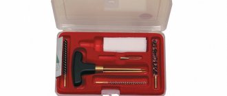
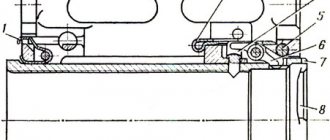
3) Inspect the accessory as specified in Art. 68, and prepare it for use during cleaning (Fig. 46).
4) Clean the bore.
Place the machine gun in the cutouts of a table for cleaning weapons or on a regular table, and if there is no table, rest the machine gun with its butt on the ground or floor.
For cleaning the bore with liquid gun lubricant
fold the tow in the form of a figure 8, place it with a figure eight cross on the end of the wiper and lay the tow fibers along the rod of the wiper; in this case, the ends of the tow should be shorter than the rubbing rod, and the thickness of the layer should be such that the rubbing with tow should be introduced into the barrel bore with a slight hand effort; pour a little liquid gun lubricant onto the tow and lightly crush the tow with your fingers. Insert a ramrod with rubbing and tow into the barrel bore and attach the canister cover (muzzle pad) to the barrel. If the barrel bore is cleaned after shooting, the compensator is screwed off. With one hand, holding the muzzle of the machine gun and the cover of the pencil case, and with the other, holding the pencil case, smoothly, without bending the ramrod, move it along the entire length of the barrel several times (when cleaning the muzzle of the barrel, remove the muzzle pad from the barrel). Take out the cleaning rod, change the tow, soak it with liquid gun lubricant and clean the bore several times in the same order. After this, thoroughly wipe the cleaning rod and wipe the bore with clean, dry tow, and then with a clean rag. Inspect the rag and, if there are visible traces of soot (blackness), rust or dirt on it, continue cleaning the barrel bore, and then wipe again with dry tow and rags. If, after wiping, the rag comes out of the barrel bore clean, that is, without blackness from powder soot or yellow color from rust, carefully inspect the bore of the barrel into the light from the muzzle and from the side of the chamber, slowly turning the barrel in your hands. In this case, pay special attention to the corners of the rifling and check whether there is any carbon deposits left in them.
Rice. 46. Machine accessory prepared for cleaning:
1 — ramrod head; 2 - pencil case; 3 - screwdriver; 4 - ramrod; 5 — pencil case cover; 6 - rubbing
Cleaning the bore with RFS solution
produce with a brush soaked in solution; then wipe the bore with tow. Continue cleaning with the RChS solution until the carbon deposits are completely removed, until a brush or tow moistened with the solution comes out of the barrel without carbon deposits or greenery. After this, wipe the bore with dry tow and then with a clean rag. The next day, check the quality of the cleaning performed and, if carbon deposits are found on it when wiping the barrel bore with a clean rag, clean again in the same order.
After cleaning the rifled part of the barrel bore, clean the chamber from the receiver side in the same manner.
Note. If, during cleaning, the cleaning rod with the cleaning rod gets stuck in the bore, you need to introduce a little heated liquid gun lubricant into the channel and after a few minutes try to remove the cleaning rod. If the cleaning rod cannot be removed, send the machine to a repair shop.
5) Rinse the gas chamber, gas tube and compensator with liquid gun lubricant or RSF solution and clean with tow (rags) using a cleaning rod or wooden stick. After cleaning the gas chamber with a RF solution, wipe it dry with a rag, inspect the barrel bore to ensure that there are no foreign objects left in it, and wipe the outside of the barrel. Wipe the gas tube dry after cleaning.
6) Clean the receiver, bolt frame, bolt, gas piston with a rag soaked in liquid gun lubricant or RFC solution, then wipe dry. If liquid gun lubricant is used for cleaning after shooting, coat the gas piston, as well as the cylindrical cutouts of the bolt with lubricant or wrap them for 3 - 5 minutes with a rag moistened with lubricant. After this, use a stick to remove the hardened powder deposits and wipe them dry.
7) Wipe the remaining metal parts dry with a rag; If parts are heavily soiled, clean them with liquid gun lubricant and then wipe dry.
 Wipe the wooden parts with a dry cloth.
48. The soldier reports to the squad commander about the completion of cleaning the machine gun; then, with the permission of the squad commander, the machine is lubricated and assembled.
47. Lubricate the machine in the following order:
1) Lubricate the bore. Screw the wiper onto the cleaning rod and place a rag soaked in lubricant on it. Introduce the rub into the bore from the muzzle and smoothly move it two or three times along the entire length of the barrel to evenly cover the bore with a thin layer of lubricant. Lubricate the chamber and compensator.
2) Coat all other metal parts and mechanisms of the machine with an oiled rag with a thin layer of lubricant. Excessive lubrication will cause parts to become dirty and may cause delays in firing.
Do not lubricate wooden parts.
After lubrication is complete, assemble the machine gun, check the operation of its parts and mechanisms, clean and lubricate the magazines and accessories, and then show the machine gun to the squad leader.
48. In the cold season, at a temperature of +5°C and below, lubricate machine guns only with liquid gun lubricant. When switching from one lubricant to another, you must carefully remove the old lubricant from all parts of the machine.
To remove grease, it is necessary to completely disassemble the machine gun, wash all metal parts in liquid gun lubricant and wipe them with a clean rag.
Note. The use of gun lubricant at air temperatures below +5° C instead of liquid gun lubricant is strictly prohibited.
49. Clean a machine brought from the cold into a warm room after 10-20 minutes (after it has sweated). It is recommended to wipe the outer surfaces of the machine gun with a rag soaked in liquid gun lubricant before entering a warm room.
50. Lubricate a machine gun that is being handed over to a warehouse for long-term storage with liquid gun lubricant, wrap it in one layer of inhibited paper, and then in one layer of waxed paper.
51. Degassing, decontamination and disinfection of machine guns are carried out according to the instructions of the unit commander.
Fire training
Fire training is training of personnel in the use of standard weapons to engage various targets in combat. It involves the study of the material part of weapons, the basics, techniques and rules of shooting, techniques and rules of throwing hand grenades, methods of reconnaissance of targets and determining ranges to them, as well as conducting shooting.
Information about the structure of small arms, handling them, caring for them and preserving them, as well as shooting techniques and rules are contained in the manuals on small arms separately for each type of small arms. Basic information from ballistics and shooting theory is presented in the shooting manual “Basics of Small Arms Shooting.”
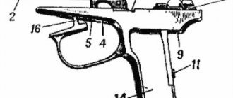
7.1. Material part of the Kalashnikov assault rifle
The Kalashnikov assault rifle is the main type of automatic small arms. It was created in 1947 by the outstanding Russian gunsmith designer M.T. Kalashnikov. After modification, the assault rifle was adopted by the Soviet Army in 1949 under the name “7.62 mm Kalashnikov assault rifle model 1947 (AK-47).” In 1963, the modernized AKM, AKMS assault rifle (with a folding stock) and the RPK, RPKS light machine guns with a folding stock and their modifications with a night sight, created on their basis, were put into production. In 1974, a new set of 5.45 mm weapons was created and began production under the leadership of M.T. Kalashnikov: AK-74, AKS-74, RPK-74, RPKS-74 and their modifications with a night sight. In 1979, the Kalashnikov assault rifle of 5.45 mm caliber AKS-74U (short) and its modifications with a night sight were developed and began production. In 1990, the 5.45 mm AK-74M (modernized) Kalashnikov assault rifle and its modifications with optical and night sights were put into service and mass production.
Kalashnikov assault rifles (Fig. 7.1) are individual weapons and are designed to destroy enemy personnel.
To defeat the enemy in hand-to-hand combat, bayonet knives are attached to the machine guns. For shooting and observation in natural night light conditions, universal night rifle sights (NSPU, NSPUM) are attached to the assault rifles. For firing from a machine gun, cartridges with ordinary (steel core) and tracer bullets are used. Rice.
7.1. Kalashnikov assault rifles:
a - AK-102; b - AKS-74; c - AKS-74U; g - AKS-74M
The machine gun fires automatic (AB) or single (OD) fire (firing with single shots). Automatic fire is the main type of fire: it is fired in short (up to five shots) and long (up to ten shots) bursts and continuously. When firing, cartridges are supplied from a box magazine with a capacity of 30 rounds. The magazines are interchangeable. Sighting range of fire is 1000 m. The most effective fire is up to 500 m. The range of a direct shot at a chest figure is 440 m, at a running figure 625 m. The rate of fire is about 600 rounds per minute. Combat rate of fire when firing in bursts is 100 rounds per minute, when firing single shots 40 rounds per minute.
The main design ballistic characteristics of the Kalashnikov series of assault rifles are given in table.
7.1. Table 7.1.
| Characteristic name | Machine model | ||||
| AK-102 | AK-104 | AK-105 | AKS-74U | AKS-74M | |
| Caliber, mm | 5,56 | 7,62 | 5,45 | 5,45 | 5,45 |
| Number of grooves, pcs. | 4 | 4 | 4 | 4 | 4 |
| Initial bullet speed, m/s | 850 | 670 | 840 | 920 | 920 |
| Weight of the machine gun with empty magazine, kg | 3,0 | 2,9 | 3,0 | 2,7 | 3,4 |
| Magazine capacity, cartridges | 30 | 30 | 30 | 30 | 30 |
| Machine length, mm | 824 | 824 | 824 | 730 | 940 |
| Length of the machine gun with the butt folded, mm | 586 | 586 | 586 | 490 | 705 |
| Barrel length, mm | 314 | 314 | 314 | 210 | 460 |
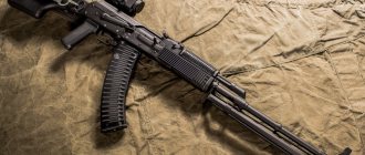
The AK-74 assault rifle consists of the following main parts and mechanisms (Fig. 7.2):
- barrel with receiver, trigger mechanism, sighting device, butt and handle;
- muzzle brake-compensator;
- gas tube with receiver lining;
- receiver cover;
- return mechanism;
- bolt carrier with gas piston;
- gate;
- handguard.
The machine gun kit includes a bayonet, a pencil case with accessories, a cleaning rod, magazines and a bag for magazines.
Rice.
7.2. Main parts and mechanisms of the AK-74 assault rifle and its accessories:
1 — barrel with receiver, trigger mechanism, sighting device, butt and handle; 2 — muzzle brake-compensator; 3 — bayonet; 4 — gas tube with receiver lining; 5 — receiver cover; 6 — return mechanism; 7 — bolt frame with rod (gas piston); 8 - shutter; 9 — pencil case with accessories; 10 — belt for carrying a machine gun; 11 - store; 12 — fore-end; 13 — ramrod
The automatic operation of the machine gun is based on the use of the energy of powder gases diverted from the barrel bore to the gas piston of the bolt frame.
The barrel (Fig. 7.3) serves to direct the flight of the bullet.
Inside the barrel has a channel with four screw rifling directed from left to top to right. The rifling serves to impart rotational motion to the bullet. The spaces between the cuts are called zeros. The distance between two opposite fields in diameter is called the caliber of the barrel. Rice.
7.3. Trunk:
a - external view of the machine gun barrel; b - section of the breech; c - trunk section; 1 — sight block; 2 — fore-end ring; 3 — front sight block; 4 — chamber; 5 — recess for the barrel pin; 6 — bullet entrance; 7 - threaded part
In the breech, the channel is smooth and shaped like a cartridge case; this part of the channel serves to accommodate the cartridge and is called the chamber. The transition from the chamber to the rifled part of the bore is called the muzzle entrance.
On the outside, the barrel has a front sight block with a protrusion for screwing on a flash suppressor, a fore-end ring, a sight block, and a cutout on the breech end for hooking the ejector. The front sight block and the sight block are secured to the barrel using pins or extrusions. The barrel is connected to the receiver by means of a pin and cannot be separated from it.
The gas chamber communicates with the barrel bore through a gas outlet.
The muzzle brake-compensator serves to increase combat accuracy and reduce recoil energy.
In small-sized and shortened Kalashnikov assault rifles (see Fig. 7.1 a, c), a flash suppressor is used instead of a muzzle brake-compensator. A flash suppressor (Fig. 7.4) reduces the magnitude of sound and flame when fired. It is a chamber with a round hole for the bullet to eject and a conical socket. At the rear, the flash arrester has an internal thread for screwing onto the threaded protrusion of the front sight base and a recess into which the latch fits; at the front there are two recesses on the conical socket for the possibility of using a cleaning rod when unscrewing the flash suppressor. Rice.
7.4. Flame arrestor:
1 — recess for the retainer, 2 — conical socket; 3 - recess for using a cleaning rod when unscrewing; 4 - internal thread
The front sight block (Fig. 7.5) is made in conjunction with the gas chamber.
It has a front sight base, a front sight, a front sight fuse, a threaded protrusion for screwing on a flash suppressor, and a retainer with a spring. The clamp prevents the flame arrester from spontaneously screwing together. The gas chamber has a gas outlet, a pipe with a channel for the gas piston and holes for the exit of powder gases. It serves to remove powder gases from the barrel and direct them to the gas piston of the bolt frame. Rice.
7.5. Front sight block:
1 - protrusion with a hole for a cleaning rod; 2 — base of the front sight; 3 - front sight; 4 — front sight fuse; 5 — clamp; 6 — thread for screwing on the flame arrester; 7 - gas chamber
The fore-end ring is used to attach the fore-end to the machine gun. It has a forend ring pin, an eyelet for a belt and a hole for a cleaning rod.
The receiver (Fig. 7.6) serves to connect the parts and mechanisms of the machine gun, to ensure that the barrel bore is closed by the bolt and the bolt is locked. The trigger mechanism is placed in the receiver. The top of the box is closed with a lid.
Rice.
7.6. Receiver:
1 - butt; 2 - transverse groove; 3 - longitudinal groove; 4 — bends; 5 — guide protrusion; 6 - jumper; 7 - reflective protrusion; 8 - cutouts; 9 — magazine latch; 10 — trigger guard; 11 — control handle
The receiver has:
- inside in the front part there are cutouts for locking the bolt, the rear walls of which are lugs, bends and guide protrusions for directing the movement of the bolt frame and bolt, a reflective protrusion for reflecting cartridges; a jumper for fastening the side walls, a protrusion for hooking the magazine and one oval protrusion on the side walls for guiding the magazine;
- in the rear part at the top there are grooves: longitudinal - for the heel of the guide rod of the return mechanism, transverse - for the receiver cover; in the rear of the receiver: a butt plate with holes for attaching the butt to the receiver;
- there are four holes in the side walls, three of them for the axes of the trigger mechanism, and the fourth for the translator trunnions;
- on the right wall there are two fixing recesses for setting the translator for automatic AB and single OD shooting;
- below there is a window for the magazine and a window for the trigger.
A butt with a swivel, a handle and a safety bracket with a magazine latch are attached to the receiver. A strap for attaching a night sight is attached to the left side wall.
The sighting device is used to aim the machine gun when shooting at targets at various distances. It consists of a sight and a front sight.
The sight (Fig. 7.7) consists of a sight block, a leaf spring, an aiming bar and a clamp.
Rice.
7.7. Aim:
1 — sight block; 2 - sector; 3 — sighting bar; 4 - clamp; 5 — mane of the sighting bar; 6 — clamp latch
The sight block has: a double-row sector to give the aiming bar a certain elevation above the front sight, eyes for attaching the sighting bar, holes for the gas tube pin; inside there is a socket for a leaf spring and a cavity for the bolt frame; on the back wall there is a semicircular cutout for the receiver cover. The sight block is placed on the barrel and secured with a pin or squeezes.
A leaf spring is placed in the sight block socket and holds the aiming bar in position.
The sighting bar has a mane with a slot for aiming and cutouts for holding the clamp in the installed position by means of a latch with a spring. On the top of the sighting bar there is a scale with divisions from 1 to 5. The numbers on the scale indicate the firing range in hundreds of meters. The letter “P” is marked on the aiming bar - a permanent sight setting that corresponds approximately to the direct shot range.
For shooting at night, self-luminous attachments are used (on the head of the aiming bar and the front sight), as well as night sights.
The clamp is put on the sighting bar and held in position with a latch. The latch has a tooth, which, under the action of a spring, slides into the cutout of the sighting bar.
The front sight is screwed into the base, which is fixed in the front sight block. There are marks on the base and block that determine the position of the front sight.
The receiver cover (Fig. 7.8) protects the parts and mechanisms placed in the receiver from contamination. On the right side it has a stepped cutout for the passage of shells reflected outward and for the movement of the bolt frame handle; at the back there is a hole for the protrusion of the guide rod of the return mechanism. The machine cover is held on the receiver using a semicircular cutout on the sight block, a transverse groove in the receiver and a protrusion of the guide rod of the return mechanism.
Rice.
7.8. Receiver cover:
1 - hole; 2 - stepped cutout
The butt and handle (Fig. 7.9) serve to facilitate the operation of the machine gun when firing.
Rice.
7.9. Butt and control handle of the machine gun:
1 — butt back cover; 2 — latch pusher; 3 — back of the butt; 4 — pencil case spring; 5 — butt lock; 6 — handle; 7 — butt latch; 8 — sling swivel; 9 — butt tip
The butt of the machine gun is made of plastic and has a tip, a sling swivel, a latch pusher, a slot for a pencil case and a back of the head with a cover. In the butt socket there is a spring for pushing out the pencil case.
To fold the butt, you need to push the latch on the left side of the butt (the latch will disengage with the tip of the butt) and turn the butt to the left around the axis until the butt is secured with a latch located in the left wall of the receiver. A light preliminary blow to the latch with a pencil case is allowed.
To tilt the butt, you need to push the latch pusher (the latch will disengage with the back of the butt) and turn the butt to the right until it is secured with a latch.
The bolt frame with a rod (Fig. 7.10) operates the bolt and trigger mechanism.
Rice.
7.10. Bolt frame with rod:
1 - channel for the shutter; 2 - safety ledge; 3 — protrusion for lowering the self-timer lever; 4 — groove for receiver bends; 5 — handle; 6 — rod; 7 - gas piston; 8 — figured cut; 9 - groove for reflective protrusion
The bolt frame has a channel inside for the return mechanism and a channel for the bolt; at the back there is a safety ledge; on the sides there are grooves for moving the bolt frame along the bends of the receiver; on the right side there is a protrusion for lowering (rotating) the self-timer lever and a handle for reloading the machine gun; at the bottom there is a shaped cutout to accommodate the leading protrusion of the bolt and a groove for the passage of the reflective protrusion of the receiver. In front of the bolt frame there is a rod with a gas piston.
The bolt (Fig. 7.11) serves to send the cartridge into the chamber, lock the barrel bore, break the primer and remove the cartridge case (cartridge) from the chamber. It consists of the bolt body, firing pin, ejector, ejector spring, ejector shaft and firing pin.
Rice.
7.11. Gate:
a - shutter body; b - drummer; c - ejector; 1 — cup for the bottom of the sleeve; 2 — cutout for ejector; 3 - leading protrusion; 4 — hole for the ejector axis; 5 — combat ledge; 6 - longitudinal groove; 7 — ejector spring; 8 — ejector axis; 9 — striker pin
The bolt has a cylindrical cup on the front cut for the bottom of the sleeve and a groove for the ejector; on the sides there are two lugs that, when the bolt is locked, fit into the cutouts of the receiver; on top there is a leading protrusion for turning the shutter when locking and unlocking; on the left side there is a longitudinal groove for the passage of the reflective protrusion of the receiver (the groove at the end is widened to ensure rotation of the bolt when locking); in the thickened part of the bolt there are holes for the ejector axis and the firing pin. Inside the bolt there is a channel to accommodate the firing pin.
The firing pin has a striker and a ledge for the pin.
An ejector with a spring and axle is designed to remove the cartridge case from the chamber and hold it until it is reflected from the receiver. The ejector has a hook for gripping the cartridge case, a socket for the spring and a cutout for the axle.
The firing pin is used to secure the firing pin and the ejector shaft.
The return mechanism (Fig. 7.12) serves to return the bolt frame with the bolt to the forward position.
It consists of a return spring, a guide rod, a movable rod and a coupling. Rice.
7.12. Return mechanism:
1 - return spring; 2 - guide rod; 3 - movable rod; 4 - coupling
The guide rod has a stop at the rear end for the spring, a heel with guide protrusions for connection with the receiver and a protrusion for holding the receiver cover.
The movable rod at the front end has bends for putting on the coupling.
A gas tube with a barrel lining (Fig. 7.13) consists of a gas tube, a front and rear ring, a barrel lining, a metal half-ring (in the case of a wooden lining) and a leaf spring.
Rice.
7.13. Gas tube with barrel lining:
1 - gas tube; 2 - guide ribs; 3 — front ring; 4 — receiver pad; 5 - rear ring; 6 — leaf spring; 7 - protrusion
The gas tube directs the movement of the gas piston rod. It has guide ribs. The front end of the gas tube is put on the gas chamber pipe.
The barrel guard protects the machine gunner's hand from burns when shooting.
The barrel lining is mounted on a gas tube between the front and rear rings; the rear ring has a protrusion into which the gas tube pin rests; The leaf spring eliminates the longitudinal rolling of the tube.
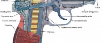
The firing mechanism (Fig. 7.14) is used to release the hammer from cocking or from the self-timer cocking, striking the firing pin, ensuring automatic or single firing, stopping firing, preventing shots when the bolt is unlocked and putting the safety on the machine gun.
Rice.
7.14. Trigger mechanism:
1 — trigger (a — combat cock; b — self-timer cock); 2 — mainspring (c — curved ends; d — loop); 3 — trigger (d — figured protrusion; f — rectangular protrusions; g — hook); 4 — single-fire sear (and — cutout); 5 — self-timer (k — sear; l — lever); 6 — self-timer spring; 7 — trigger retarder spring; 8 — trigger retarder (n — latch; p — front protrusion); 9 — spring whispered single firing; 10 — translator (p — axle; s — sector); 11 — tubular axis; 12 - axles
The trigger mechanism is placed in the receiver, where it is attached by three interchangeable axes, and consists of a hammer with a mainspring, a hammer retarder with a spring, a trigger, a single-fire sear with a spring, a self-timer with a spring, a translator and a tubular axis.
The trigger with a mainspring is used to strike the firing pin. The trigger has a combat cock, a self-timer cock, trunnions and a hole for the axle. The mainspring is put on the trigger pins and acts with its loop on the trigger, and with its ends on the rectangular protrusions of the trigger.
The trigger retarder is designed to slow down the forward movement of the trigger in order to improve the accuracy of fire when conducting automatic firing from stable positions. It has front and rear lugs, an axle hole, a spring and a latch.
The trigger serves to keep the hammer cocked and to release the hammer. It has a shaped protrusion, an axle hole, rectangular protrusions and a tail. The figured protrusion of the trigger holds the hammer cocked.
The single-shot sear is designed to hold the trigger in the rearmost position after firing if the trigger was not released during single-shot shooting. It is on the same axis with the trigger. The single-firing sear has a spring, a hole for the axis and a stepped protrusion, which is covered by the translator sector during automatic firing and locks the sear. In addition, the stepped protrusion limits the forward rotation of the translator sector when the translator is put on safety.
The self-timer is used to automatically release the trigger from the self-timer cocking when firing in bursts, as well as to prevent the trigger from being released when the barrel is open and the bolt is not closed. It has a protrusion to hold the trigger on the self-timer, a lever to rotate the self-timer, and a spring.
The spring is located on the same axis as the self-timer. Its short end is connected to the self-timer, and its long end runs along the left wall of the receiver and fits into the annular grooves on the axes of the self-timer, hammer and trigger, keeping the axes from falling out.
The translator is designed to set the machine gun to automatic or single firing, as well as to the safety catch. It has a sector with trunnions that fit into the holes in the walls of the receiver. The lower position of the translator corresponds to setting it for single firing (OD), the middle one for automatic firing (AB), the upper one for the safety.
The forend (Fig. 7.15) serves for ease of holding and to protect the machine gunner’s hands from burns.
The forend is attached to the barrel from below using the forend ring and to the receiver by means of a protrusion that fits into the receiver socket. The forend has a groove for a cleaning rod. Rice.
7.15. Handguard:
1 — groove for cleaning rod; 2 - protrusion; 3 — screen; 4 - finger rest
The metal shield of the forend is designed to reduce heat during shooting.
The magazine (Fig. 7.16) is used to place cartridges and feed them into the receiver. It consists of a plastic body, cover, locking plate, spring and feeder.
Rice.
7.16. Shop:
1 — locking plate; 2 - spring; 3 - support protrusion; 4 — feeder; 5 — hook; 6 — body; 7 - cover
The magazine body connects all parts of the magazine; its side walls have bends on top (at the neck) to keep the cartridges from falling out and protrusions that limit the rise of the feeder; on the outer surface there are two vertical grooves for attaching the adapter, on the front wall there is a hook, and on the back there is a supporting protrusion, through which the magazine is attached to the receiver. On the rear wall of the case there is a control hole to determine whether the magazine is fully loaded with cartridges.
The bottom of the case is closed with a lid. The lid has a hole for the locking plate to protrude.
A feeder and a spring with a locking bar are placed inside the housing. The feeder is held at the upper end of the spring by an internal bend on the right wall, and has a protrusion that provides a staggered arrangement of cartridges in the magazine. The locking bar is permanently attached to the lower end of the spring and, with its protrusion, keeps the magazine cover from moving.
The carrying belt (Fig. 7.17) is used to carry the machine gun in the combat and traveling position.
Rice.
7.17. Carrying strap:
1 - belt loop; 2 - loop; 3 — buckle; 4 - carabiner
The carrying belt consists of a belt strip, at one end of which a carabiner is attached using a metal plate and ring, the other end of the tape is made in the form of a loop with a metal buckle and loop. Due to the loop and buckle, the length of the belt can be adjusted taking into account the individual characteristics of the machine gunner.
The magazine bag (Fig. 7.18) is used to store and carry magazines and accessories.
Rice.
7.18. Shop bag:
1 — side pocket valve; 2 - gort; 3 — bag cover; 4 - store; 5 — clamp; 6 - oiler
The inside of the bag consists of compartments that hold magazines.
On the side wall of the bag there is a pocket for an oil can and a pencil case with accessories; it is closed with a flap that is held in place by a collar fastened with a pocket latch. A pencil case with accessories is placed in the small compartment of the pocket.
On the outer surface of the back wall of the bag there are two carrying loops sewn for putting the bag on a waist belt, and below the loops there is a soft pad for the convenience of wearing the bag on a belt.
A bayonet (Fig. 7.19) is attached to the machine gun before an attack and serves to defeat the enemy in hand-to-hand combat, and can also be used as a knife, saw (for cutting metal) and scissors (for cutting wire).
Rice.
7.19. Bayonet knife:
a - old design; b - new design; 1 - blade; 2 - cutting edge; 3 — sharpened edge; 4 - hole; 5 - saw; 6 — belt hook; 7 - belt; 8 - latch; 9 — metal tip; 10 - longitudinal grooves; 11 - connecting screw; 12 — handle; 13 - ring
To carry a bayonet-knife on the waist belt, use a sheath (Fig. 7.20). If necessary, they are used together with a bayonet knife to cut wire.
Rice. 7.20. Bayonet with scabbard