It is PROHIBITED to neutralize mines installed with MVE-NS.
Security measures.
Storage and transportation of MVE-NS is carried out only in factory sealing.
Only serviceable fuses without mechanical damage and having safety checks and seals are allowed for use.
Fuses are transported to the installation site separately from the mines. In this case, the fuse blocks must be connected by rubber rings.
When pulling out the safety pin, the MVE-NS fuse must be held in your hand with the sleeve with the pinning mechanism facing away from you.
After screwing the BI into the mine's ignition socket, if the LED stops blinking, immediately leave the installation site.
If the LED does not blink after pulling the pin or lights up continuously, then work with the MVE-NS fuse stops and it must be replaced.
PROHIBITED:
— use MVE-NS that fell from a height of more than 1.5 m (both packaged and unpacked);
— use fuses that have mechanical damage;
- move fuses and mines at the installation site and remove current sources from the fuses after screwing the explosive device onto the mine.
MVE-72 mine fuse.
The MVE-72 mine fuse is designed to detonate anti-personnel fragmentation mines when the enemy interacts with its break target sensor.
Basic performance characteristics.
Type - electromechanical. Cocking time - 50 - 180 sec. Weight - 600 g.
Case diameter - 65 mm.
Height - 150 mm;
The current source is element 373.
Temperature range of application - from -40 to +50 degrees.
Combat work time is 4 months.
Device.
The MVE-72 fuse consists of a housing in which an electronic unit and a pyrotechnic switch are mounted, a cup from a current source, a pinning mechanism connected to the electronic unit by wires, and a break sensor. There is a plug on the top of the case. A thread of a grating igniter is attached to it, which activates the pyrotechnic switch. To connect a break sensor, there is a socket on the housing, closed with a plug. The glass is screwed into the lower part of the body, which has a thread.
The pricking mechanism (NM) is similar to that discussed above.
The break sensor consists of an enameled winding wire with a diameter of 0.14 mm, folded in half. The length of the double wire is 50 m. A plug is attached to the ends of the wire, which is plugged into a socket on the fuse body. For ease of storage and use, the sensor is wound on a closed reel.
Operating principle.
When the grater is pulled out, the grater igniter is triggered, which ignites the pyrotechnic moderator. After 50 - 80s, the powder charge ignites. The pressure of the powder gases actuates the pyrotechnic switch and connects the current source to the electronic unit. No more than 100 s after connecting the current source, the combat capacitor is charged. Thus, 150 - 180 seconds after pulling out the grater, the fuse is transferred to the firing position.
When the wire of the break sensor breaks, the electronic unit ensures the discharge of a combat capacitor to the electric igniter of the pinning mechanism. The electric igniter is triggered, the gases push the striker, which pierces the mine igniter capsule (MD-5M fuse) and causes the mine to explode.
Preparing for installation.
In preparation for installation, a current source is installed in the fuse. To do this you need:
— check the suitability of element 373 by expiration date and inspect it to ensure its serviceability (an element is considered suitable if it has at least 6 months left before its expiration date and does not have electrolyte leakage or bulging walls);
- clean the bottom and central contact of the element with a knife;
— unscrew the glass from the fuse body and insert the element into the glass centrally with the contact outward;
- screw the glass with the element inserted into it into the fuse body.
Installation of mines with MVE-72.
The MVE-72 fuse can be used with mines OZM-72, OZM-4, MON-50, MON-100, MON-200, OZM-3 and POMZ-2M.
To detonate mines MON-50, MON-100, MON-200 and POMZ-2M, the MVE-72 fuse is used with an MD-5M fuse.
The MVE-72 fuse is installed and camouflaged next to the mine. The breakage sensor is stretched over the terrain in the area affected by the mine, and is mounted on vegetation or poles at a height of 10-30 cm above the ground surface.
To install anti-personnel fragmentation mines with MVE-72 you must:
— mark (with flags) the installation sites of the mine and breakage sensor;
— set (point at the target and secure) a mine;
— install the MVE-72 in the hole next to the mine (tie the fuse with twine or soft wire to the device on which the mine is attached) so that access to the plug is provided;
— remove the plug from the clamp in the coil and secure it temporarily to the wires of the pinning mechanism;
— unwind the wires of the break sensor by pulling them out of the coil in the direction of its axis, moving from the mine to the marked installation locations of the break sensor; when stretching the wires, they are fastened to the ground with slack every 5-10 m by wrapping the wires around tall plants, tufts of grass, branches or pegs; simultaneously with the stretching of the wires, marking signs (flags) are sequentially removed; the end of the wires is also secured;
— after stretching the wires to their full length, approach the mine and release the plug;
- check the integrity of the wires with an M-57 ohmmeter, connecting it to the plug contacts - the ohmmeter needle should deviate to zero; in case of a wire break, replace the break sensor (for replacement there are 4 spare break sensors for every 16 fuses);
— remove the plug from the MVE-72 socket and install the plug into the socket until it fails;
- unscrew the OZM-72 (OZM-3, OZM-4) mine sleeves and screw the MVE-72 pinning mechanism in its place, unscrewing the plug from it; when installed with mines MON-50, MON-100, MON-200 and POMZ-2M, screw the MD-5M fuse into the MVE-72 pop-up mechanism, unscrew the plug from the mine's ignition socket and screw the MD-5M fuse into the mine's ignition socket;
— unscrew the plug from the fuse body and pull out the thread attached to the plug to its full length;
— disguise the mine and fuse;
- holding the fuse with one hand, pull out the grater with the other hand by the plug with a sharp movement;
— without touching the sensor wires, move away from the mine.
IT IS PROHIBITED to neutralize unguided mines installed with MVE-72.
Explosive device NVU-P (“Hunting”).
The NVU-P (“Hunting”) non-contact explosive device is intended for use with anti-personnel fragmentation mines when mining areas.
Basic performance characteristics.
Type – non-contact, wire-controlled.
Target sensor type - seismic
The type of mines with which it is used is OZM-72, MON-50.
The number of mines used with one NVU-P device is 5 pcs.
The response radius for a moving person is from 5 to 15 m.
The type of long-range cocking mechanism is two-stage mechanical and electronic.
Long-range cocking time - from 6 to 36 minutes.
Combat work time is up to 3 months.
The self-destruction time is when the last mine explodes or when the current source is depleted.
Installation time and minutes for a crew of three people - from 30 to 50 minutes.
The weight of the NVU-P device is 4.2 kg.
Overall dimensions: diameter - 155 mm; height - 362 mm.
Temperature range of use is from -40 to +50 degrees.
Warranty shelf life (without power source) is 10 years.
The state control method is by wire using the MZU remote control.
Contents of the kit.
Electronic unit - 1 pc.
Target sensor (seismic receiver SV-20P) - 1 pc.
Block of pinning devices - 1 pc.
Fuze MUV-4 - 1 pc.
Pinning mechanism - 1 pc.
Control cable 100 m long - 1 pc. for 4 NVU-P devices.
Replaceable current source (battery 373) - 6 pcs.
Test block with plug - 1 pc. for 4 NVU-P devices.
MZU control panel (available in
separate packaging) - 1 pc. for 12 NVU-P devices.
Device.
The electronic unit is designed to amplify electrical signals coming from the target sensor6, process them and sequentially connect one of the five pin devices to the combat capacitor of the actuator in accordance with their markings. It also provides remote control of the state of the NVU-P device and its self-destruction.
The electronic unit contains a receiving device, a logical block, an actuator, a distribution device, a current source with a voltage converter, an electronic long-range cocking mechanism, an indication device, a remote control mechanism and a self-destruction device.
The electronic unit is mounted in a metal case, covered with a removable metal casing. The casing is pressed against the housing cover using hinged locks. There are two rubber rings on the casing for attaching the TNT block. At the bottom of the case there is a compartment for the current source. In the upper part of the body on the cover there are: a threaded bushing for screwing on MUV-4; connector for connecting a control cable or connecting cable for a radio line actuator; light indicator for monitoring the serviceability of the electronic long-range cocking mechanism and the presence of supply voltage when checking the functionality of the electronic unit; connector for connecting a target sensor; connector for connecting a block of pin devices or a test block; screw clamps for fastening the block of pinning devices; output wires of the self-destruction device for connecting the pricking mechanism. In the transport position, the threaded bushing and connections for connecting the control cable and target sensor are closed with screw caps.
The target sensor is designed to convert seismic signals generated in the ground when a person passes into electrical ones. The target sensor has a metal cylindrical body with a conical tip. Inside the housing there is a moving coil suspended on flat springs in a constant magnetic field. The target sensor has a connector for connecting to the electronic unit. In the transport position, the connector is closed with a screw cap.
The block of pointing devices (BNU) is designed to initiate capsules of OZM-72 mine igniters or MD-5M fuses when pulses are received from the actuator of the electronic unit. The BNU consists of a plastic case, five numbered pin devices, a connector for connecting to the electronic unit and a removable plastic casing.
The pinning device has a plastic case, which houses a two-wire connecting line 20 m long, an electric igniter and a firing pin.
MUV-4 is designed to ensure safe installation of NVU-P and acts as a mechanical long-range cocking mechanism (the first stage of protection) with a long-range cocking time of 1-30 minutes.
The impaling mechanism (NM), the MD-5M fuse and the TNT block are intended for the destruction (self-destruction) of the electronic unit after the last mine is triggered or when the current source is depleted.
The wire block is designed to test the functionality of the electronic unit. It has a plastic case with five numbered indicator lights and a pin connector for connecting to an electronic unit.
The test plug is designed to activate the electronic long-range cocking mechanism when checking the operability of the NVU-P. The plug is screwed onto a threaded bushing instead of MUV-4.
The MZU mine control panel is designed to check the status and control the position (safe, combat) of the electronic unit.
The control cable is designed to connect the electronic unit to the control panel. The control cable is made of SPP-2 sapper wire and has connectors at the ends for connection to the control panel and electronic unit.
Operating principle.
After the MUV-4 combat and safety pin is pulled out and the long-range fuse arming time has expired (1-30 min), the MUV-4 is triggered and the striker closes contact S1, connecting the current source to the electronic long-range arming mechanism and the display unit. In this case, the indicator light H1 lights up. After the long-range cocking time has elapsed (5-7 minutes), contact S2 closes and the voltage through contacts S3 of the remote control mechanism, closed when testing the NVU-P device, is supplied to the voltage converter and self-destruction device. The H1 indicator light goes out, the NVU-P device goes into the firing position.
When a target appears in the response zone of the NVU-P device, seismic signals arising in the ground are converted by the target sensor into electrical signals and are sent to the input of the receiving device. When the threshold voltage level is reached at the input of the receiving device, the logical block for processing received signals begins to function with a processing period of 3 seconds. When the necessary information accumulates in it during this period, the actuator is triggered.
The combat capacitor of the actuator is discharged to the electric igniter of the first point-on device. The first mine is blown up. When the target reappears in the response zone, the NVU-P device processes the incoming signals in the same sequence and the combat capacitor is discharged to the electric igniter of the second pointing device.
After the fifth mine is detonated, the self-destruction device emits a current pulse to the impaling mechanism. The MD-5M fuse is triggered, the TNT block is detonated and the electronic unit is destroyed.
The self-destruction device also triggers when the voltage of the current source drops to 6.5 V.
Security measures.
The transfer of the NVU-P into a combat position is carried out by one person on command.
The final camouflage of the NVU-P and moving to a safe distance from it is carried out in no more than 6 minutes after pulling out the MUV-4 safety pin.
When installing the NVU-P device in a controlled version, the control cable is laid over its entire length, and the distance from the location of the control cable connector to the electronic unit must be at least 90-100 m.
It is allowed to approach the installation site of the NVU-P no earlier than 5 minutes after it has been moved to a safe position using the MZU remote control.
PROHIBITED:
— search and remove NVU-P installed in the unmanaged version, as well as
NVU-P, which is not moved by the control panel to a safe position;
— install NVU-P closer than 200 m from existing power lines, electric power plants, radio and radar stations and sources of constant seismic interference;
— use faulty NVU-P;
— reuse the block of pinning devices.
Preparing for installation.
Preparing the NVU-P device for installation involves equipping the electronic unit with a current source and checking its functionality.
To equip the electronic unit with a current source, you must:
— remove the casing from the electronic unit;
— check the suitability of element 373 by appearance, warranty period of storage using the combined device Ts-4313. The discharge current of the element being tested must be at least 1.5 A, the duration of the test with the Ts-4313 device is no more than 1 s. It is not permissible to use elements that have less than 6 months left before the expiration of the warranty storage period, with swollen walls, traces of corrosion and electrolyte leaks on the body;
— insert six elements into the compartment under the current source in accordance with the markings on the pads and secure them around the perimeter with a rubber ring;
— close the electronic unit with a casing, securing it with locks.
The functionality of the NVU-P must be checked by a team of two people in the following order:
— remove the cover from the connector plug for the control cable of the electronic unit and connect the control cable socket to it, having first unscrewed the plug from it;
— unscrew the plug from the second socket of the control cable and connect the socket to the plug of the TO PRODUCT connector on the MZU control panel;
— in accordance with the instructions on the inside of the cover of the MZU remote control, check the condition of the electronic unit and move it to the on position (contact S3 closes);
— connect the control cable from the electronic unit and the MZU control panel;
— screw the previously removed covers onto the corresponding connectors;
— unscrew the cap from the connector plug for connecting the target sensor;
— connect the target sensor using the connector socket to the electronic unit, having previously unscrewed the plug from the socket and screwed the socket nut all the way;
— insert a test block into the connector for connecting the block of pinning devices;
— bury the target sensor with its conical part into the ground in a vertical position, ensuring reliable contact of the sensor body with the ground;
— unscrew the cover from the threaded bushing of the electronic unit and screw the test plug onto it; the indicator light located on the housing cover should light up, which indicates the serviceability of the electronic long-cocking mechanism. After 4-7 minutes, the indicator light goes out, the electronic unit is switched to the firing position;
— check the functionality of the NVU-P device, for which: the 1st calculation number is located near the electronic unit and monitors the state of the light indicators on the test block (during the entire test, the 1st number should not produce seismic interference in the ground); The 2nd calculation number (starting from a distance of 30-40 m) passes two to five meters from the electronic unit, while all the light indicators on the test block should light up in sequence; if not all indicator lights come on during one pass, a second pass should be made;
— after checking the NVU-P, remove the verification block, unscrew the test plug, disconnect the target sensor, screw the cover onto the connectors and place the NVU-P in the shipping box.
Installation.
The NVU-P device with mines can be installed in autonomous and controlled versions. In the autonomous version, NVU-P should be installed only with self-destruction, in the controlled version - with or without self-destruction. When installing NVU-P in a controlled version, it is necessary to make an accurate reference to local landmarks using a map of the location of the control cable connector and the installation locations of the electronic unit and min.
When installing NVU-P with OZM-72 mines, the mines are located at a distance of at least 5 m from the electronic unit and from each other. With an autonomous installation option, the fifth mine can be installed in close proximity to the electronic unit.
When installing NVU-P with MON-50 mines, the mines are located at a distance of 3-5 m from each other, and the electronic unit is installed at a distance of 10-20 m from the mines towards the enemy.
To install NVU-P in a standalone version, you must:
— using the MZU remote control, move NVU-P to the on position;
— dig a pit measuring 0.5x0.25 m and depth 0.3-0.4 m to install the electronic unit;
- in accordance with the selected installation scheme, dig holes for mines and trenches for laying wires for pinning devices in them; the depth of the trenches must be at least 10 cm;
- lay mines;
- remove the electronic unit from the packaging and make sure that it is equipped with current sources and is in working order, to do this, screw a test plug onto the threaded bushing (the indicator light should light up), then unscrew it (the indicator light should go out) and not earlier than Connect the target sensor to the electronic unit for 5 minutes;
— insert the block of pin-type devices into the connector socket of the electronic unit and secure it with screw clamps;
— check the presence and reliability of fastening the MUV-4 fuse pin;
— unscrew the test plug from the threaded bushing and screw the MUV-4 fuse onto it;
— prepare NVU-P for self-destruction, for which a pinning mechanism is connected to the output wires of the electronic unit by twisting; insulate the connection points, screw the MD-5M into the pinning mechanism, then into the socket of the TNT block; use rubber rings to secure the protyl block to the casing of the electronic unit;
— install the electronic unit in the pit and bury the target sensor in a vertical position with the conical part into the ground;
— remove the casing from the block of pinning devices and separate the pinning devices in accordance with their markings and the installation diagram for the mines;
— without damaging the insulation, lay the wires of the splicing devices in ditches and cover them with soil;
— screw the flashing devices onto the bushings with igniter capsules of the OZM-72 mines (screw the MD-5M fuses into the flashing devices, and then into the ignition sockets of the MON-50 mines);
— disguise mines and ditches with wires;
— place the electronic unit in a pit in a horizontal position and cover it with soil, leaving an undisguised MUV-4 fuse pin;
- on command, pull out the combat pin and then the safety pin of the MUV-4 fuse;
— carry out final camouflage of the installation site of the electronic unit and immediately retreat to a safe distance.
The time it takes to transfer the NVU-P into combat mode from the moment the combat pin is pulled does not exceed 6 minutes.
Before installing the NVU-P device in a controlled version, it is necessary to move the remote control mechanism of the electronic unit to the off position, for which:
— equip the control panel (CP) of the MZU with a current source (element 373);
— connect the control panel and the electronic unit with a control cable;
— put switch B1 on the control panel in the ON position, switch B2 in position II and make sure that the remote control mechanism is in the on position;
— put switch B1 in the OFF position;
— disconnect the control cable from the control panel and the electronic unit. Close the cable connectors with plugs.
In accordance with the chosen mining scheme, install NVU-P and mines in the same way as when installing NVU-P in an autonomous version, then dig a ditch at least 10 cm deep for laying the control cable and a hole for the connector for connecting the launcher, connect the control cable to the electronic block, place it in a ditch and cover it with soil. The cable connector in the hole is not masked. A pole or flag marks the location of the connector.
To transfer the NVU-P to a combat position it is necessary:
— screw the MUV-4 fuse onto the threaded bushing of the electronic unit and pull out the combat and safety pins from it;
— disguise the installation location of the electronic unit;
— go to the location of the free connector of the control cable and connect it to the control panel;
— turn switch B1 to ON position. and make sure that NVU-P is in a safe (off) position - the remote control arrow should be in the green sector of the scale;
— move switch B2 to position I, press it all the way and release the START button. The remote control arrow should be in the red sector of the scale;
— turn switch B1 to the OFF position, disconnect the cable connector from the remote control, screw the plug into the connector and screw the cover onto the remote control socket;
— disguise the location of the control cable connector and move away from the mining area.
Neutralization.
It is allowed to neutralize (remove) NVU-P devices installed in a controlled version, for which it is necessary:
— prepare the MZU control panel for operation;
- based on the location data of the minefield section and the location of the control cable connectors, use an induction mine detector (IMP-2) to find the control cable connector, dig a hole and remove the connector. The search should be carried out by one person, approaching the border of the minefield from the rear side and without crossing it;
— connect the control cable connector to the MZU remote control;
— put switch B1 on the remote control to position ON, switch B2 to position II. The remote control arrow should be located in the red sector of the scale - the NVU-P device is in the firing position. Press and release the START button. The remote control arrow must be within the green sector of the scale - the NVU-P device is moved to a safe position; if the NVU-P device has not moved to the safe position, switch switch B2 to position I and, after waiting 15 seconds, press the START button all the way again and release it. If the electronic unit is not moved to a safe position, further neutralization of the NVU-P device is PROHIBITED;
— after moving the NVU-P to a safe position, turn off the MZU remote control and disconnect the control cable connector from it;
- no less than 5 minutes after moving the NVU-P to a safe position, begin searching with a mine detector for installation sites for the electronic unit and mines;
— dig out the electronic unit and unscrew the MUV-4 fuse from it;
— disconnect the connector of the block of pinning devices and the pinning mechanism;
— remove the TNT block from the casing of the electronic unit, unscrew the MD-5M fuse and the impaling mechanism;
— unscrew the pinning devices from the mines;
- remove the electronic unit, target sensor and mines from the ground, remove the KD N8-A from the mines (for the MON-50 mines the MD-5M or MD-2 fuse);
— disconnect the target sensor and control cable from the electronic unit;
— dig out the control cable and lay it in the bay;
— remove elements 373 from the electronic unit housing;
- clear all NVU-P elements and mines from the ground and place them in packages.
IT IS PROHIBITED to remove mines that have damage that prevents screwing together the pinning devices and removing the N8-A CD (for MON-50 mines, the MD-5M or MD-2 fuse). These mines, after the minefield is removed, are destroyed by overhead charges at the installation site.
MVE-72 fuze
FuzesSend to a friend
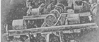
Let's consider a more complex fuse - MVE-72 (electronic mine fuse developed in 1972). This is a fuse with a break target sensor and a long-range cocking mechanism. The appearance of the fuse is shown in the photo.
1 – plug, 2 – pinning mechanism wires, 3 – target break sensor socket, 4 – housing, 5 – cup. A drawing of the complete fuse is shown in the following picture.
The designations of the previous figure are retained here. 6 – pinning mechanism – a widespread design element of modern mines. A cross-section of the pinning mechanism is shown below.
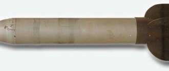
1 – connecting wires, 2 – housing, 3 – electric igniter, 4 – powder charge, 5 – firing pin, 6 – MD-5M fuse. The last part of the fuse is a coil containing a break target sensor - 50 m of double-folded winding wire with a diameter of 0.14 mm with a soldered connector. The appearance of the coil is shown in the figure.
Here 1 is a coil, 2 is a connector, 3 is a wire (target sensor). The MVE-72 fuse is used with fragmentation mines of the MON, OZM and POMZ series, but can be used with any explosive devices designed to be initiated by MD-2 and MD-5M fuses or directly by the impaling mechanism. The sequence of preparing the fuse for use is as follows: 1. Select a place to install the mine and target sensor (in the mine affected area). 2. Set a mine. 3. Select a location to install the fuse. The maximum distance from the mine to the fuse is determined by the length of the wires of the pinning mechanism. 4. Secure the target sensor connector in the immediate vicinity of the fuse installation site to a peg, a tuft of grass or other local objects. 5. Unwind the target sensor wire in the mine affected area, securing it at a height of 10 - 30 cm every 5 - 10 meters behind pegs, tufts of grass or local objects. 6. Check the integrity of the target sensor by connecting an M-57 ohmmeter or any other ohmmeter (tester) to the connector. 7. Check the suitability of the power source (element 373 - “large round battery”). Before the warranty period expires, the battery must remain in storage for at least 6 months, and there must be no damage to the battery case. 8. Unscrew the glass from the fuse, insert the battery into the glass with the central electrode facing out, and screw the glass with the battery into the fuse. 9. Equip the pinning mechanism with a fuse and install the mine in the point or screw the pinning mechanism onto the thread of the mine nipple. 10. Remove the plug covering the target sensor connector on the fuse body and connect the target sensor to the fuse. 11. Unscrew the plug of the fuse grater mechanism, carefully unwind the traction cord, disguise the mine and fuse, and with a sharp movement pull out the grater cord. After this, you must immediately leave the mine installation site. After 1 - 3 minutes the fuse will be armed.
What happens inside the fuse after the grater is pulled out? The grating composition ignites and ignites the pyromoderator - a slowly burning low-gas composition. The pyrotechnic retarder burns for no more than 100 seconds and turns on the pyrotechnic switch, thereby connecting the battery to the electronic circuit of the fuse. At this moment, the combat capacitor begins to charge, the charging time of which depends on its capacity and the resistance of the long-range charging resistor connected in series with it. The capacitor charges for several tens of seconds, after which the mine goes into a combat position - into target standby mode. In this mode, a small operating current passes through the target sensor, indicating its integrity.
If the target sensor breaks, the current through it stops, which is a signal for the fuse to fire: the combat capacitor is discharged to the electric igniter of the pinning mechanism. The electric igniter ignites the powder charge, and the firing pin of the pinning mechanism, under the influence of powder gases, pierces the fuse primer.
Disarming mines installed with MVE-72 fuses is prohibited.
Let's consider the situation if “it’s impossible, but it’s really necessary.” This is called extreme mine clearance. The most difficult thing in this matter is to detect the mine before it detects you.
If you are forced to covertly move through territory where there are supposed to be mines, your choice of tactics is limited and is completely determined by the available equipment. For complete happiness you need a mine detector and a probe. Let's say you have them. Standing still, use a mine detector to check the ground in front of you, as far as you can reach. If nothing is found, walk through the tested area, holding the dipstick in front of you and holding it with two fingers, as shown in the photo. The tip of the probe should be as close to the ground as possible.
With this position of the probe, the fingers very well “hear” its contact with the metal of the stretch mark and do not allow, by applying excessive force, to break the wire of the target break sensor. Of course, you will not have any speed, but there is only one alternative: rely on luck and go ahead.
But then you found a wire and identified it as a broken target sensor. What to do next? Option number one (the best) is to go around or step over. Unfortunately, this is not always acceptable. Option number two – mark and bypass. This happens more often, but not always. Option number three (worst) is to neutralize it. This is what we will look at now.
So, in front of you is a broken sensor wire and the decision has been made to defuse the mine. First of all, you need to trace the wire to the fuse. We should not forget that there may be high-explosive pressure mines along the wire. When moving along a wire, as when moving along a tripwire, you must be extremely careful and search for mines using a mine detector, probe, and visually, while not letting the target sensor wire out of your eyes.
And finally, you, covered in cold sweat and scaring away mice and other forest creatures, approach the place where the wire goes underground. The fuse (and the mine) are somewhere very close. Very carefully, with your fingers, you dig up the ground, trying to feel the fuse body without breaking the thin wire of the sensor. The sensitivity of your fingers is heightened beyond belief. Finally the fuse and the mine are in front of you. Then everything is quite simple: you unscrew the fuse from the mine along with the firing mechanism, remove the fuse from the pin and cut its wires. ALL!
There is, however, another way to overcome a mine with this fuse. The method is faster, but also much more dangerous. In short, not for everyone. Once you have found the target sensor, trace it 2 - 3 meters away from your path and, having carefully stripped the sensor wires, twist them together. Then, having traced the target sensor 2 - 3 meters to the other side of the path, do the same and cut out a section of the sensor between two twists. As you understand, if the insulation is poorly stripped, these actions will lead to an explosion, and an attempt to properly strip the wires can lead to a break in one of them with the same consequences. In addition, the mine will not remain neutralized and may be triggered if the target sensor section connected to the fuse breaks.
Author: A. Kostyukov
Comments on the article (3)
Tags: MVE-72, pinning mechanism
The presented article presents the point of view of the author who wrote it, and has no direct relation to the point of view of the leading section. This information is presented as historical material. We are not responsible for the actions of site visitors after reading the article. This article was obtained from open sources and published for informational purposes. In case of unknowing copyright infringement, the information will be removed after receiving a corresponding request from the authors or publishers in writing.
Anti-personnel mine MON-90. Operating instructions (2 pages)
Rice. 6.
Aiming the MON-90 mine
After aiming the mine, you must:
— unscrew the plug of the mine's ignition socket;
— screw an EDP-r electric detonator (EDP) or an MD-5M fuse into the ignition socket (Fig. 7);
A
b
V
Rice. 7.
Installation in mine:
A
) electric detonator EDP-r;
b
) electric detonator EDP;
c
) VZD-6ch fuse with MD-5M fuse:
1
- mine;
2
— electric detonator EDP-r;
3
— electric detonator EDP;
4
- bushing;
5
— fuse MD-5M;
6
— fuse VZD-6ch
— onto the nipple of the MD-5M fuse, screw the pinning mechanism of the MVE-72 fuse or the VZD-6ch delayed action fuse (VZD-144);
- disguise the mine.
In winter conditions, with snow cover up to 30 cm thick, the mine is placed on the lid of a box on the ground surface and masked with a layer of loose snow. With snow cover more than 30 cm thick (Fig. it is necessary to dig a hole in the snow according to the size of the box, install the box and compact the snow around it, install and aim the mine. After installing the explosive device in the ignition nest, the mine is masked with a layer of loose snow. The thickness of the masking layer on the side the enemy should be no more than 20 cm.
Rice. 8.
Scheme of installing the MON-90 mine in snow more than 30 cm deep
The MON-90 mine can be used in various installation options:
— a controlled minefield with a UMP-3 anti-personnel minefield control kit;
— controlled single mines or groups of mines, undermined by demolition machines;
— with an electromechanical mine fuse MVE-72 with a break drive;
- as a delayed-action mine with a VZD-144 (VZD-6ch) fuse.
The most effective is considered to be the use of a mine in a controlled version.
In the controlled version, the mine is installed with an EDP-r electric detonator (EDP) and is exploded via wires with a UMP-3 set, a blasting machine or other current sources. The mine explosion is carried out in accordance with the instructions for using the UMP-3 kit and blasting machines.
Preparation and activation of VZD-144 and VZD-6ch fuses is carried out in accordance with the instructions for their use. The deceleration time of the fuse is selected in accordance with the conditions for completing the assigned task.
Installation of mines with MVE-72 fuse
To install a mine with an MVE-72 fuse (Fig. 9), you must: install and aim the mine and turn on the MVE-72 fuse in accordance with the instructions for its use.
Rice. 9.
Installation diagram of MON-90 mine with MVE-72 fuse
INSTALLATION OF A CONTROLLED MINEFIELD WITH UMP-3 KIT
The UMP-3 kit allows you to install a field of MON-90 mines with control of the state of the minefield (combat or safe) and selective explosion of mines or only selective explosion of mines. Using the kit, you can install and maintain a controlled minefield consisting of four sections in combat readiness. The location of minefield sections on the ground and their sizes depend on local conditions, the task being performed, and the number of mines.
The distance between mines in rows is determined by the nature of the terrain and should not exceed 75 m. The distance between rows should not be less than 25 m. Actuating devices are installed behind the mines at a distance of at least 3 m.
Installation of a controlled minefield with the UMP-3 kit is carried out by a platoon of sappers with the laying of control lines using the PMZ-4 minelayer or manually. Two sections carry out the breakdown of sections of the minefield, installation of actuators and mines in the sections (each section in two sections). One department lays control lines and sets up a control point.
Before installing a section of a minefield, the squad commander with two crew numbers divides the rows of mines with milestones, and flags mark the installation sites of mines, sighting milestones and actuators. The preparation of the UMP-3 kit and its installation are carried out in accordance with the instructions for its use. Then the squad leader with two numbers sets and aims the mines.
After checking the serviceability of the kit, at the command of the platoon commander, all personnel are removed from the mine affected area, and specially assigned crew numbers connect the mines to the actuators and mask them.
After removing the crew numbers that connected the mines from the affected area, the platoon commander personally checks the serviceability of the minefield.
INSTALLATION OF A MINEFIELD OF MIN-90 MINES WITH MVE-72 FUSES
A minefield of MON-90 mines with MVE-72 fuses must be installed only in cases where other options for installing a minefield are impossible, since the length of the break drive of the MVE-72 fuse does not allow mines to be installed at a distance of more than 30 m. This significantly reduces the efficiency use of MON-90 mines and increases their consumption by 2–2.5 times.
The minefield is established by a sapper squad of seven people. The squad leader with one crew number breaks a row of mines with milestones, flags mark the places where the mines are installed and the direction of stretching of the break drive. The distance between mines in rows is 30 m, the distance between rows should not be less than 35–40 m. The breakdown is carried out over the entire minefield. In one go, the department sets 6 minutes.
All operations for installing a mine and a fuse with a breakable number drive are carried out simultaneously according to the commands of the squad commander.
Each crew number goes to the mine installation site, indicated by a flag, installs the mine and the fuse. The squad leader with one crew number aims the mines. After this, each crew number stretches and secures the break drive towards the enemy in the direction of the flag installed on the left border of the affected area, not reaching it 1 m (to the right of it), turns to the right and moves along the front to the flag indicating the left border of the adjacent mine. . Having made sure that the neighbor on the right has passed and stretched the drive, he removes the flag, stretches the remaining part of the drive on the reel in the direction of the mine and moves towards the mine.
After turning on the fuse, the crew number saves the fuse plug and hands it over to the squad leader.
The next entry is made in the same order. In this case, the flag indicating the drive limit of the outermost mine installed during the first approach is not removed. It is removed by the first number when stretching the drive.
When installing a two-row minefield, the first row, counting from the enemy, is first installed, then the second.
Approximate time standards for laying mines and minefields are given in the appendix.
MINE DISPOSAL
To neutralize a mine installed with an EDP-r (EDP) electric detonator, you must:
— disconnect the main wires from the control panel (blasting machine);
- remove the disguise from the mine;
— unscrew the electric detonator from the mine’s ignition socket;
- remove the mine from the installation site.
The neutralization of a mine installed with delayed-action fuses VZD-144 and VZD-6ch is carried out in accordance with the instructions for their use.
In the event that the situation does not allow the establishment of a milestone, the mine must be aimed in the direction of the expected appearance of the enemy using local landmarks located at a distance of 50–90 m from the mine.
Rice. 6. Aiming the MON-90 mine
After aiming the mine, you must:
— unscrew the plug of the mine's ignition socket;
— screw an EDP-r electric detonator (EDP) or an MD-5M fuse into the ignition socket (Fig. 7);
A
b
V
Rice. 7. Installation in mine:
A
) electric detonator EDP-r;
b
) electric detonator EDP;
c
) VZD-6ch fuse with MD-5M fuse:
1
- mine;
2
— electric detonator EDP-r;
3
— electric detonator EDP;
4
- bushing;
5
— fuse MD-5M;
6
— fuse VZD-6ch
— onto the nipple of the MD-5M fuse, screw the pinning mechanism of the MVE-72 fuse or the VZD-6ch delayed action fuse (VZD-144);
- disguise the mine.
In winter conditions, with snow cover up to 30 cm thick, the mine is placed on the lid of a box on the ground surface and masked with a layer of loose snow. With snow cover more than 30 cm thick (Fig. it is necessary to dig a hole in the snow according to the size of the box, install the box and compact the snow around it, install and aim the mine. After installing the explosive device in the ignition nest, the mine is masked with a layer of loose snow. The thickness of the masking layer on the side the enemy should be no more than 20 cm.
Rice. 8. Scheme of installing the MON-90 mine in snow more than 30 cm deep
The MON-90 mine can be used in various installation options:
— a controlled minefield with a UMP-3 anti-personnel minefield control kit;
— controlled single mines or groups of mines, undermined by demolition machines;
— with an electromechanical mine fuse MVE-72 with a break drive;
- as a delayed-action mine with a VZD-144 (VZD-6ch) fuse.
The most effective is considered to be the use of a mine in a controlled version.
In the controlled version, the mine is installed with an EDP-r electric detonator (EDP) and is exploded via wires with a UMP-3 set, a blasting machine or other current sources. The mine explosion is carried out in accordance with the instructions for using the UMP-3 kit and blasting machines.
Preparation and activation of VZD-144 and VZD-6ch fuses is carried out in accordance with the instructions for their use. The deceleration time of the fuse is selected in accordance with the conditions for completing the assigned task.
Installation of mines with MVE-72 fuse
To install a mine with an MVE-72 fuse (Fig. 9), you must: install and aim the mine and turn on the MVE-72 fuse in accordance with the instructions for its use.
Rice. 9. Installation diagram of the MON-90 mine with MVE-72 fuse
INSTALLATION OF A CONTROLLED MINEFIELD WITH UMP-3 KIT
The UMP-3 kit allows you to install a field of MON-90 mines with control of the state of the minefield (combat or safe) and selective explosion of mines or only selective explosion of mines. Using the kit, you can install and maintain a controlled minefield consisting of four sections in combat readiness. The location of minefield sections on the ground and their sizes depend on local conditions, the task being performed, and the number of mines.
The distance between mines in rows is determined by the nature of the terrain and should not exceed 75 m. The distance between rows should not be less than 25 m. Actuating devices are installed behind the mines at a distance of at least 3 m.
Installation of a controlled minefield with the UMP-3 kit is carried out by a platoon of sappers with the laying of control lines using the PMZ-4 minelayer or manually. Two sections carry out the breakdown of sections of the minefield, installation of actuators and mines in the sections (each section in two sections). One department lays control lines and sets up a control point.
Before installing a section of a minefield, the squad commander with two crew numbers divides the rows of mines with milestones, and flags mark the installation sites of mines, sighting milestones and actuators. The preparation of the UMP-3 kit and its installation are carried out in accordance with the instructions for its use. Then the squad leader with two numbers sets and aims the mines.
After checking the serviceability of the kit, at the command of the platoon commander, all personnel are removed from the mine affected area, and specially assigned crew numbers connect the mines to the actuators and mask them.
After removing the crew numbers that connected the mines from the affected area, the platoon commander personally checks the serviceability of the minefield.
INSTALLATION OF A MINEFIELD OF MIN-90 MINES WITH MVE-72 FUSES
A minefield of MON-90 mines with MVE-72 fuses must be installed only in cases where other options for installing a minefield are impossible, since the length of the break drive of the MVE-72 fuse does not allow mines to be installed at a distance of more than 30 m. This significantly reduces the efficiency use of MON-90 mines and increases their consumption by 2–2.5 times.
The minefield is established by a sapper squad of seven people. The squad leader with one crew number breaks a row of mines with milestones, flags mark the places where the mines are installed and the direction of stretching of the break drive. The distance between mines in rows is 30 m, the distance between rows should not be less than 35–40 m. The breakdown is carried out over the entire minefield. In one go, the department sets 6 minutes.
All operations for installing a mine and a fuse with a breakable number drive are carried out simultaneously according to the commands of the squad commander.
Each crew number goes to the mine installation site, indicated by a flag, installs the mine and the fuse. The squad leader with one crew number aims the mines. After this, each crew number stretches and secures the break drive towards the enemy in the direction of the flag installed on the left border of the affected area, not reaching it 1 m (to the right of it), turns to the right and moves along the front to the flag indicating the left border of the adjacent mine. . Having made sure that the neighbor on the right has passed and stretched the drive, he removes the flag, stretches the remaining part of the drive on the reel in the direction of the mine and moves towards the mine.
After turning on the fuse, the crew number saves the fuse plug and hands it over to the squad leader.
The next entry is made in the same order. In this case, the flag indicating the drive limit of the outermost mine installed during the first approach is not removed. It is removed by the first number when stretching the drive.
When installing a two-row minefield, the first row, counting from the enemy, is first installed, then the second.
Approximate time standards for laying mines and minefields are given in the appendix.
MINE DISPOSAL
To neutralize a mine installed with an EDP-r (EDP) electric detonator, you must:
— disconnect the main wires from the control panel (blasting machine);
- remove the disguise from the mine;
— unscrew the electric detonator from the mine’s ignition socket;
- remove the mine from the installation site.
The neutralization of a mine installed with delayed-action fuses VZD-144 and VZD-6ch is carried out in accordance with the instructions for their use.
Prohibited! Defuse a mine installed with an MVE-72 fuse.
SECURITY MEASURES