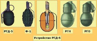
Design
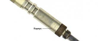
UZRG fuse
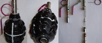
It is a metal case, inside of which there is an igniter primer, a moderator in the sleeve (powder pulp filling the central channel) and a detonator primer. The retarder bushing is the basis for assembling the entire igniter structure. The firing mechanism of the fuse consists of a firing pin, a mainspring, a safety pin and a safety bracket[1][5][6].
Disassemble the UZRG
is strictly prohibited[1].
Options
After the Great Patriotic War, several more advanced fuse models were developed:
- UZRGM
(Russian
Unified
Ignition of
Hand
Grenade Modernized )
a
with TNRS
) inside the aluminum moderator bushing sleeve[8]. - UZRGM-2
- unlike UZRG, contains a less hygroscopic retarding composition with a burning rate that does not depend on the ambient temperature [9].
One of the main differences from the basic design was the replacement of the powder pulp in the moderator with a special smokeless composition [5].
2.1. Unified hand grenade fuse modernized UZRGM
Rice.
7. Unified modernized hand grenade fuse (UZRGM) UZRGM grenade fuse
(modernized unified hand grenade fuse) (Fig. 7) is intended to explode the explosive charge in F-1, RGD-5 and RG-42 grenades.
The impact mechanism serves to ignite the igniter primer. It consists of a hammer tube, a connecting sleeve, a guide washer, a mainspring, a firing pin, a firing pin washer, a trigger lever and a safety pin with a ring.
The impact mechanism tube is the basis for assembling all parts of the igniter.
The connecting sleeve serves to connect the fuse to the grenade body. It is placed on the bottom of the impact mechanism tube.
The guide washer is a stop for the upper end of the mainspring and directs the movement of the firing pin. It is fixed in the upper part of the impact mechanism tube.
UZRGM device
It consists of a striking mechanism and the fuse itself.
In official use, the striker is constantly cocked and held by the trigger lever fork.
The trigger lever is connected to the percussion mechanism tube by a safety pin. Before throwing a grenade, the plastic plug is turned out and the fuse is screwed in its place.
Rice. 8. Impact mechanism
1 – impact mechanism tube; 2 – guide washer; 3 – mainspring; 4 – drummer; 5 – striker washer; 6 – release lever; 7 – safety pin with ring; 8 – connecting sleeve.
After pulling the pin, the position of the fuse parts does not change.
Rice. 9. Fuse:
9 – primer – igniter; 10 – retarder bushing; 11 – moderator; 12 – capsule – detonator.
At the moment the grenade is thrown, the trigger lever separates and releases the firing pin. The firing pin, under the action of the mainspring, pierces the igniter capsule. A beam of fire from the primer ignites the moderator and, after passing through it, is transmitted to the detonator primer. The explosion of the detonator capsule initiates the detonation of the explosive charge. The explosion of the explosive charge crushes the grenade body into fragments.
Interaction of UZRGM parts
(Fig. 10, 11)
1. The pin is pulled out, the grenade is thrown, the lever is separated, the firing pin punctures the primer - the igniter.
Rice. 10.
2. The powder composition of the moderator burns out, the detonator primer fires
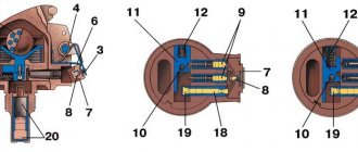
Rice. 11. Fig. 12. Impact-remote fuse UDZ
2.1.
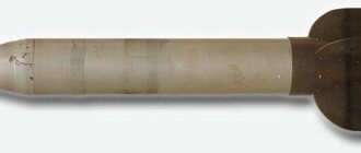
Impact-remote fuse UDZ
(Fig. 12)
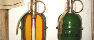
RGO and RGN hand fragmentation grenades are equipped with a shock-remote UDZ fuse.
Rice. 13. Impact-remote fuse device UDZ 1 – housing.
Puncture safety mechanism:
- 2 – release lever;
- 3 – striker with a sting;
- 4 – mainspring;
- 5 – ring with a pin;
- 6 – bar;
- 7 – plug;
- 8 – primer – igniter.
Long-range cocking mechanism:
- 9 – powder fuses;
- 10 – primer – igniter;
- 11 – engine;
- 12 – spring.
Target Sensor:
- 13 – sting;
- 14 – spring;
- 15 – sleeve;
- 16 – bushing;
- 17 – cargo.
Self-liquidator mechanism:
- 18 – moderator;
- 19 – capsule – detonator.
Detonation unit:
- 20 - capsule - detonator.
Interaction of parts and mechanisms
Initial position.
In the initial position, the striker with the sting (3) and the plug with the igniter primer (7) are held by the trigger lever. The trigger lever is connected to the igniter body by a safety pin. The engine (11) with the igniter capsule (10) is offset relative to the tip (13) and is held by the powder fuses stoppers (9), its spring (12) is in a compressed state. The bushing (16) under the influence of the spring (14) presses the load (17).
Rice. 14 Interaction of parts and mechanisms impact-remote fuse UDS
When preparing a grenade for throwing, the trigger lever is pressed tightly with your fingers to the body of the grenade, the ends of the safety pin are straightened with the fingers of your free hand, then it is pulled out by the ring, while the position of the fuse parts does not change. Position of parts and mechanisms in official circulation
(Fig. 14).
At the moment the grenade is thrown, the trigger lever separates and releases the striker with the sting (3) and the bar (6). The plug (7) with the igniter capsule comes out of the igniter housing socket. The firing pin, under the action of the mainspring (4), pierces the igniter primer (8) with its sting.
The fire beam ignites the powder press-fit fuses (9) and the pyrotechnic composition of the self-liquidator moderator (18).
After 1-1.8 seconds. The powder compositions of the fuses burn out and their stoppers, under the influence of springs, disengage with the engine (11).
The engine, under the influence of the spring (12), moves into the firing position.
The long-range cocking mechanism prevents the grenade from being detonated if it accidentally falls from the hand.
Interaction of parts and mechanisms when throwing and meeting a grenade with an obstacle (surface)
When meeting an obstacle (surface), the load (17) shifts in the direction of the inertial force component and acts on the sleeve (16). The bushing, overcoming the resistance of the spring (14), displaces the tip, which pierces the igniter primer (10). The fire beam is transmitted to the detonator capsule (20), which causes the explosive charge to detonate.
In case of failure, the fuse will operate in inertia after 3.3 - 4.3 seconds.
the moderator composition burns out, the detonator cap (19) of the self-destructor ignites, causing the detonation unit to explode. Read full summary Hand grenades
Notes
- ↑ 123
Shooting manual. Hand fragmentation grenades (RG-42, RGD-5, F-1). / Under the supervision of V. M. Saiko. - Moscow: Military Publishing House of the USSR Ministry of Defense., 1957. - 24 p. - Karpenko A.
Hand grenade F-1 (lemon) // Domestic hand grenades. - Moscow: Tseykhgauz, 2006. - P. 38. - 88 p. — ISBN 5-9771-0001-9. - Pribylov B.V.
F-1 hand fragmentation grenade with Koveshnikov fuse // Hand grenades (handbook). - Moscow: Arktika 4D, 2004. - S. . — 144 p. — ISBN 5-902835-01-1. - Article “Purpose and combat properties of hand fragmentation grenades F-1, RGD-5, RGN, RGO” on the website voennizdat.com
- ↑ 1 2 3 Pribilov B. Kravchenko E.
Hand and rifle grenades. - Moscow: Arctic 4D, 2008. - P. 540-541. — 776 p. — ISBN 978-5-902835-04-2. - Novikovsky E.A.
Design and purpose of parts and mechanisms of UZRGM // Domestic small arms, grenade launchers, hand fragmentation grenades and ammunition / Pichkovsky S.I., Skobelev A.O. - Barnaul: AltSTU, 2009. - P. 108. - Article “Hand fragmentation grenades and fuses used with them” on the website www.zakon-grif.ru
- Dick V.N.
RGD-5 hand grenade with UZRGM fuse // Explosives, gunpowder and ammunition of domestic production. - Minsk: Okhotkontrakt, 2009. - T. 1. - P. 202. - 280 p. — 1000 copies. — ISBN 978-985-6911-02-9. - Shiryaev D.
Striking with fragments (Russian) // World of weapons: magazine. - 2005. - June (vol. 06, no. 03). — P. 36-43. - ISSN 1607-2009.
UZRGM
“UZRGM” GRENADE FUSE
(modernized unified hand grenade fuse).
UZRGM is intended for explosion of a bursting charge (Fig. 4). It consists of a striking mechanism and the fuse itself.
The impact mechanism serves to ignite the igniter primer. It consists :
hammer tube, connecting tube, guide washer, mainspring, firing pin, firing pin washer, trigger lever, safety pin with ring.
The impact mechanism tube is the basis for assembling all parts of the igniter.
The connecting tube serves to connect the fuse to the grenade body. It is put on the lower part of the impact mechanism tube.
The guide washer is a stop for the upper end of the mainspring and directs the movement of the firing pin. It is fixed in the upper part of the impact mechanism tube.
The mainspring serves to provide the striker with the energy necessary to puncture the igniter primer. It is put on the striker and its upper end rests against the guide washer, and its lower end rests against the striker washer.
The firing pin serves to puncture and ignite the igniter primer. It is placed inside the impact tube.
The trigger lever serves to hold the firing pin in the cocked position (the mainspring is compressed). The trigger lever is held on the hammer tube by a safety pin.
The safety pin passes through the holes in the eye of the trigger lever and the walls of the impact mechanism tube. It has a ring for pulling it out.
The fuse itself serves to explode the explosive charge of the grenade.
It consists of : a moderator bushing, an igniter primer, a moderator and a detonator primer.
The moderator sleeve in the upper part has a thread for connection with the percussion mechanism tube and a socket for the igniter capsule, inside there is a channel in which the moderator is placed, and on the outside there is a groove for attaching the primer sleeve - the detonator.
The igniter primer is designed to ignite the moderator.
The retarder transmits a beam of fire from the igniter primer to the detonator primer. It consists of a pressed low-gas composition.
The detonator capsule is used to explode the explosive charge of the grenade. It is placed in a sleeve attached to the bottom of the retarder bushing.
ATTENTION : The fuse is always in the firing position. to disassemble fuses and check the operation of the striking mechanism !!!
Operation of grenade parts and mechanisms.
Before throwing a grenade. Take the grenade out of the bag, unscrew the plug from the tube, and screw the fuse in its place until it stops.
The parts of the firing mechanism are in the following position: The firing pin is cocked and held in the upper position by the fork of the trigger lever, connected to the firing mechanism tube by a safety pin. The ends of the safety pin are spread apart and firmly hold it in the fuse (1).
When throwing a grenade. The grenade for throwing is taken so that the trigger lever (4) is pressed against the body of the grenade with your fingers. Without releasing the lever, the safety pin (3) is pulled out and the grenade is thrown at the target. After pulling out the pin, the position of the parts does not change; the hammer (6) is held in the cocked position by the trigger lever (4), which is released from the connection with the hammer mechanism tube (2), but is pressed against it with the fingers. At the moment the grenade is thrown, the trigger lever separates from the grenade and releases the firing pin. The firing pin, under the action of the mainspring (5), strikes (pricks) the igniter primer (9) and ignites it. The beam of fire from the igniter capsule ignites the moderator / remote part of the fuse / (11) and, having passed through it, is transmitted to the detonator capsule (12). The detonator cap explodes and detonates the explosive charge of the grenade. The body of the grenade bursts, and fragments of the body and fuse fly in different directions, hitting enemy personnel.